Image Processing Systems

a technology of image processing and image, applied in the field of image processing systems, to achieve the effect of optimizing the benefits of tma driving, reducing peak and typical luminance, and more efficient operation

Inactive Publication Date: 2009-12-31
CAMBRIDGE DISPLAY TECH LTD
View PDF20 Cites 18 Cited by
  • Summary
  • Abstract
  • Description
  • Claims
  • Application Information

AI Technical Summary

Benefits of technology

[0004]In a conventional passive matrix display the display is driven line-by-line and hence a high drive is required for each line because it is only illuminated for a fraction of the frame period. MLA techniques drive more than one line at once and in TMA techniques all the lines are driven simultaneously and an image is built up from a plurality of successively displayed subframes which, when integrated in the observer's eye, give the impression of the desired image. The required luminescence profile of each row (line) is built up over a plurality of line scan periods rather than as an impulse in a single line scan period. Thus the pixel drive during each line scan period can be reduced, hence extending the lifetime of the display and / or reducing the power consumption due to a reduction of drive voltage and reduced capacitive losses. This is because OLED lifetime reduces with the pixel drive (luminance) to a power typically between 1 and 2 but the length of time for which a pixel must be driven to provide the same apparent brightness to an observer increases only substantially linearly with decreasing pixel drive. The degree of benefit depends in part upon the correlation between the groups of lines driven together.
[0038]In some preferred embodiments the display driving comprises current driving. Thus, for example, one axis of the display, say a column axis, may be provided with a current drive (source or sink) and the other axis of the display, say a row axis, may be provided with a ratio drive to divide the total drive on the first axis in accordance with a ratio (for each row) determined by the drive values for the second display axis. In some preferred embodiments the axis which does not have a ratioed drive is provided with a pulse width modulated drive. This is especially useful for OLED displays as it allows the drives to the first and second axes of the display effectively to be decoupled from one another.

Problems solved by technology

The problem is to determine sets of row and column drive signals for the subframes so that a set of subframes approximates the desired image.

Method used


Image

  • Image Processing Systems
  • Image Processing Systems
  • Image Processing Systems

Examples


Embodiment Construction

of Post-Processing Calculations

[0066]We will first give the calculations employed, and then the reasoning behind them.

[0067]For each sub-frame p calculate:

Cpmax=max(Cpx) over all x,  (1)

Rpmax=max(Rpy) over all y,  (2)

and, for a colour display,

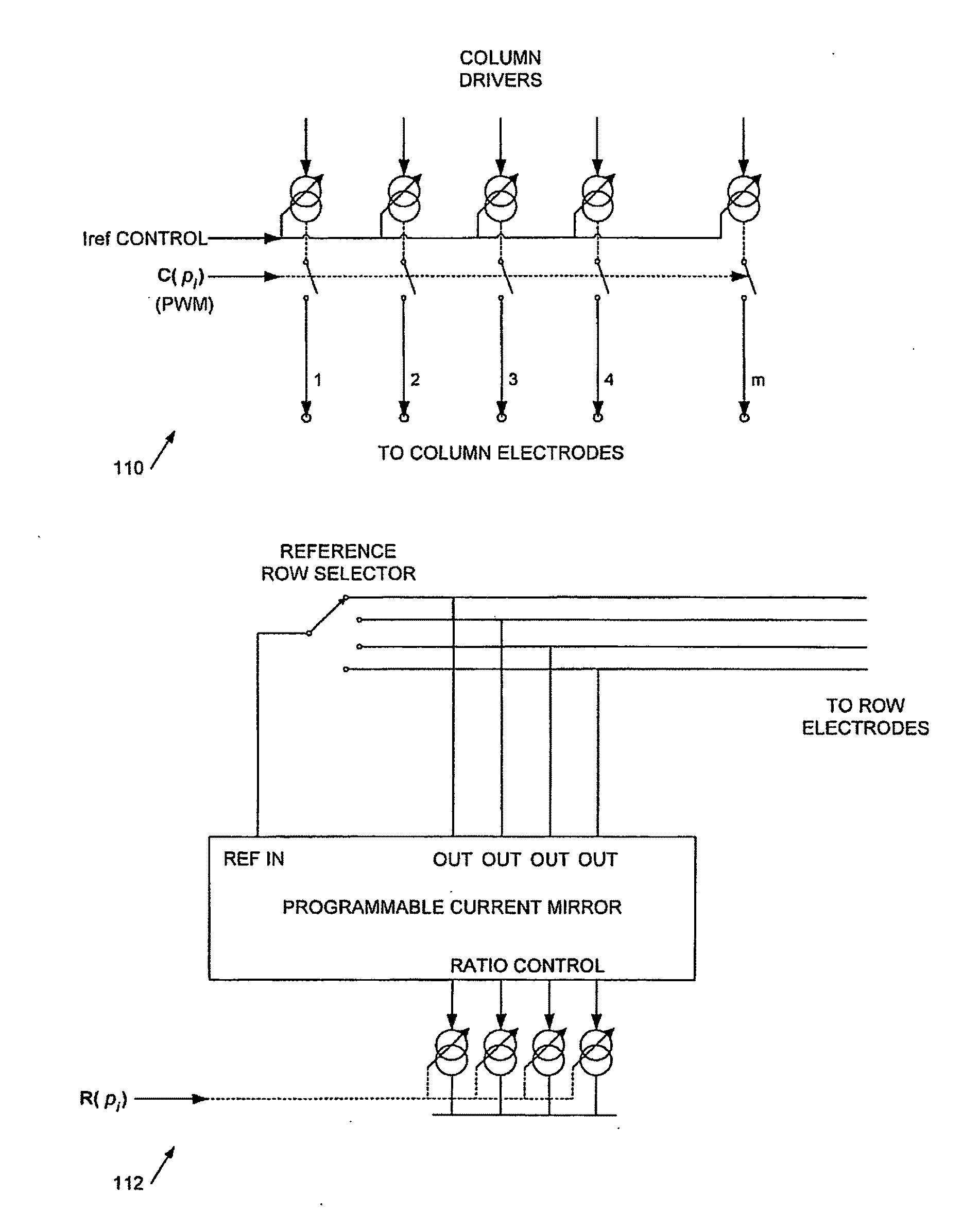
Cpsum=Ired∑x=0,3,6…357Cpx+Igreen∑x=1,4,7…358Cpx+Iblue∑x=2,5,8…359Cpx29(3)

where Ired, Igreen, and Iblue are the relative (reference) drive levels of the red, green and blue pixels (10-bit values) compared to a nominal reference of, in this example, 29.

[0068]The aim in this example is to minimise the pixel luminances and therefore duration of each sub-frame is proportional to RmaxCmax (the luminance of the brightest pixel). Thus we calculate the sum:

T=∑pCpmaxRpmax(4)

[0069]The PWM clock period for a sub-frame, tp is given by:

tp=220CpmaxT(5)

[0070]The minimum value of Rmax×tp is 1024; the maximum value is 220−1. Where Rmax×tp is less than 512 tp should be rounded to zero; where it is between 512 and 1024 tp should be rounded up such that Rmax×tp equ...


PUM


Abstract

This invention generally relates to image processing systems. More particularly it relates to systems and methods for displaying images using multi-line addressing (MLA) or total matrix addressing (TMA) techniques, and to techniques for post-processing of data for display generated by these techniques. Embodiments of the invention are particularly useful for driving OLED (organic light emitting diode) displays. We describe a method of driving an electroluminescent display to display an image using a plurality of temporal sub-frames, data for a said sub-frame comprising a first set of drive values (R;C) and second set of drive values (C;R) for driving respective first and second axes of said display, a said sub-frame having an associated sub-frame display time. The method comprises: determining a said sub-frame display time for a displayed sub-frame responsive to one or more of said drive values for the sub-frame; and driving said display to display said temporal sub-frames for respective said sub-frame display times.

Description

[0001]This invention generally relates to image processing systems. More particularly it relates to systems and methods for displaying images using multi-line addressing (MLA) or total matrix addressing (TMA) techniques, and to techniques for post-processing of data for display generated by these techniques. Embodiments of the invention are particularly useful for driving OLED (organic light emitting diode) displays.[0002]We have previously described how techniques for multi-line addressing (MLA) and total matrix addressing (TMA) in particular using non-negative matrix factorisation (NMF) may be advantageously employed in OLED display driving (see in particular our International application PCT / GB2005 / 050219, hereby incorporated by reference in its entirety). We now describe further improvements to these techniques in which, broadly speaking, multiple frame sets are employed for noise reduction and improved image quality. Background prior art is described in GB2327798A; EP 0953956A;...

Claims


Application Information

Patent Timeline
Patent Type & Authority Applications(United States)
IPC IPC(8): G09G5/00G09G3/30
CPCG09G3/2022G09G3/3216G09G3/3283G09G2360/16G09G2320/043G09G2330/025G09G2310/0205G09G3/3208G09G3/3674G09G3/3681G09G3/3644G09G2310/0202H01L2924/12044Y02B20/30H10K59/35H10K59/17
Inventor SMITH, EUAN CHRISTOPHER
Owner CAMBRIDGE DISPLAY TECH LTD
Why Eureka
Try Eureka