Optical Unit and Projection Type Display Apparatus for Displaying an Image

Inactive Publication Date: 2009-12-31
HITACHI LTD
View PDF8 Cites 4 Cited by
  • Summary
  • Abstract
  • Description
  • Claims
  • Application Information

AI Technical Summary

Benefits of technology

[0020]Preferably, in the projection type display apparatus for displaying an image according to the present invention, in the case where the brightness level of the image signal is smaller than a predetermined first value, the control unit controls the iris unit to maximize the stop-down level.
[0021]Preferably, in the projection type display apparatus for displaying an image according to the present invention, in the case where the brightness level

Problems solved by technology

However, in the case of displaying a dark image, reduction of contrast occurs.
Therefore, in the case where the apparatus is used for household when watching a movie and the like in a home theat

Method used


Image

  • Optical Unit and Projection Type Display Apparatus for Displaying an Image
  • Optical Unit and Projection Type Display Apparatus for Displaying an Image
  • Optical Unit and Projection Type Display Apparatus for Displaying an Image

Examples


first embodiment

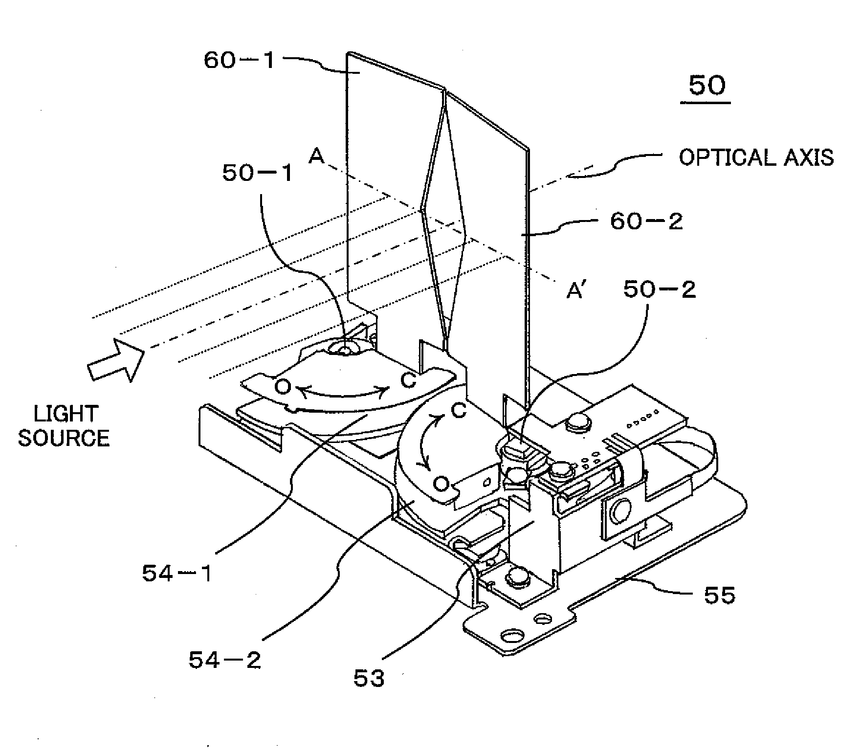
[0051]An embodiment of the present invention will be described with reference to FIG. 5. FIG. 5 is a diagram for explaining a configuration of the iris unit of the embodiment of the projection type display apparatus for displaying an image according to the present invention. The reference numeral 50 denotes the iris unit, 50-1 denotes a rotation center of the left light shielding plate of the iris unit 50, 50-2 denotes a rotation center of the right light shielding plate of the iris unit 50, 51-1 denotes the position of the left light shielding plate when the iris is fully opened, 51-2 denotes the position of the right light shielding plate when the iris is fully opened, 52-1 denotes the position of the left light shielding plate when the iris is fully closed, and 52-2 denotes the position of the right light shielding plate when the iris is fully closed.

[0052]In FIG. 5, the light emitted from the light source unit (not shown) located on the lower side is directed to the upper side t...

second embodiment

[0079]Another embodiment of the present invention will be described with reference to FIG. 9. FIG. 9 is a diagram for explaining a configuration of the iris unit of the embodiment of the projection type display apparatus for displaying an image according to the present invention. The reference numeral 50′ denotes the iris unit, 50-1′ denotes the rotation center of the left light shielding plate of the iris unit 50′, 50-2′ denotes the rotation center of the right light shielding plate of the iris unit 50′, 51-1′ denotes the position of the left light shielding plate when the iris is fully opened, 51-2′ denotes the position of the right light shielding plate when the iris is fully opened, 52-1′ denotes the position of the left light shielding plate when the iris is fully closed, 52-2′ denotes the position of the right light shielding plate when the iris is fully closed, 3′ denotes the reflex lens, 4′ denotes the first integrator, 5′ denotes the second integrator, θ′ denotes the maximu...


PUM


Abstract

To suppress the reduction of contrast caused by reduction of contrast in the case where a projection type display apparatus for displaying an image is used in a dark place. In a projection type display apparatus for displaying an image which includes a liquid crystal display element unit that modulates and emits incident light, an illumination optical system that allows emission light emitting from a light source to enter the liquid crystal display element unit, and a projection optical system that projects the emission light emitting from the liquid crystal display element unit to a screen, an optical unit includes an iris unit in which light shielding plates shut the amount of light entering the liquid crystal display element unit to be narrowed down as the brightness level of image light projected from the projection optical system is lower, and an open/close angle of each light shielding plate is set at smaller than 90 degrees.

Description

BACKGROUND OF THE INVENTION[0001](1) Field of the Invention[0002]The present invention relates to a projection type display apparatus for displaying an image such as a liquid crystal projector apparatus, and particularly to an optical unit using an illumination-system iris.[0003](2) Description of the Related Arts[0004]With an increasing size of a household television screen in these days, the television screen has been widely used for a home theater in many cases. A liquid crystal projector as a projection type display apparatus for displaying an image has also become widespread for use as a household display device or a household movie projector (home theater) for displaying a broadcasting television image.[0005]In the projection type display apparatus for displaying an image such as a liquid crystal projector, emission light from a light source is projected to a screen while being modulated using a liquid crystal panel as a spatial light modulation element. The liquid crystal pro...

Claims


Application Information

Patent Timeline
IPC IPC(8): G03B21/14
CPCG03B21/14H04N9/3197H04N9/315H04N9/3105G03B21/208
Inventor KIMURA, NOBUYUKI
Owner HITACHI LTD
Why Eureka
Try Eureka