Rotary actuator

a technology of rotary actuators and actuators, which is applied in the direction of printers, instruments, camera focusing arrangements, etc., can solve the problems of difficult to obtain a torque level sufficient to direct drive the rotation, and achieve the effect of reducing the weight of the photographic lens

Inactive Publication Date: 2009-12-31
RICOH IMAGING COMPANY
View PDF21 Cites 28 Cited by
  • Summary
  • Abstract
  • Description
  • Claims
  • Application Information

AI Technical Summary

Benefits of technology

[0006]The present invention provides a rotary actuator which can be incorporated in a photographic lens of a camera to be used as a drive source for an AF mechanism, and which makes it possible to achieve miniaturization and a weight reduction of the photographic lens.
[0018]According to the present invention, a rotary actuator is achieved, in which torque in the circumferential direction is produced by magnetic force between the coil body and the multi-polar magnet by controlling currents supplied to the coil body. Accordingly, a reduction gear device becomes unnecessary, and miniaturization and a weight reduction of the actuator become possible. In addition, a high-voltage circuit for driving a motor such as an ultrasonic motor becomes unnecessary. Therefore, in the case where a rotary actuator according to the present invention is used as a drive source for an AF mechanism of a photographic lens, miniaturization of the AF mechanism becomes possible, so that miniaturization and a weight reduction of the photographic lens can be achieved.

Problems solved by technology

However, in small DC motors and small ultrasonic motors, it is difficult to obtain a level of torque sufficient to (directly drive) rotate the focus cam ring, and accordingly, a reduction gear device is typically employed with the DC or ultrasonic motor so that torque of the motor is converted into high torque to be transferred to the focus cam ring via the reduction gear device.
Therefore, the internal space of the photographic lens needs to accommodate both the reduction gear device and the high-voltage circuit, which has been an obstacle to miniaturization and a weight reduction of the photographic lens.

Method used


Image

  • Rotary actuator
  • Rotary actuator
  • Rotary actuator

Examples


embodiment 2

[0047]As shown in FIGS. 5 and 6, in the second embodiment of the rotary actuator 10A, a multi-polar magnet 1A thereof serving as a stator (which corresponds to the multi-polar magnet 1 of the rotary actuator 10) includes a plurality of (two) circular-arc-shaped pieces 11A and 11B made of an isotropic magnetic material which are arranged and fixed in a circle to form a circular ring with north and south poles of magnetized pieces of the plurality of circular-arc-shaped pieces 11A, 11B being alternately arranged at regular intervals. Additionally, in a similar manner to that in the first embodiment of the rotary actuator, a coil body 2A, which is a integral combination of the plurality of coils 21 and the coil holder 22, is loosely fitted on the multi-polar magnet 1A. FIG. 6 is a schematic cross-sectional plan view of the second embodiment of the rotary actuator. In the multi-pole magnetized type of multi-polar magnet 1A, although each south-pole or north-pole magnetized portion there...

embodiment 3

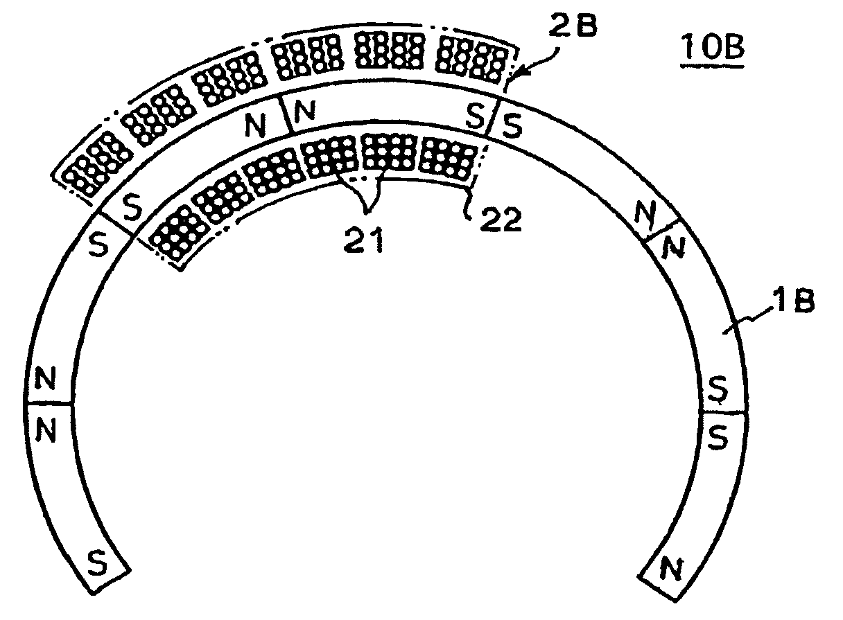
[0052]In each of the first and second embodiments of the rotary actuators, the multi-polar magnet can make the coil body 2 (2A or 2B) that serves as a mover rotate through the circumference of the multi-polar magnet (360 degrees) since the multi-polar magnet is shaped into a circular ring. Namely, the multi-polar magnet can make the coil body 2 (2A or 2B) rotate infinite times; however, in the case where the rotary actuator is configured so that the mover (coil body) only needs to be rotatable within an angular rotation range smaller than 360 degrees, the multi-polar magnet can be formed into an arc shape (i.e., does not have to be formed into a circular ring).

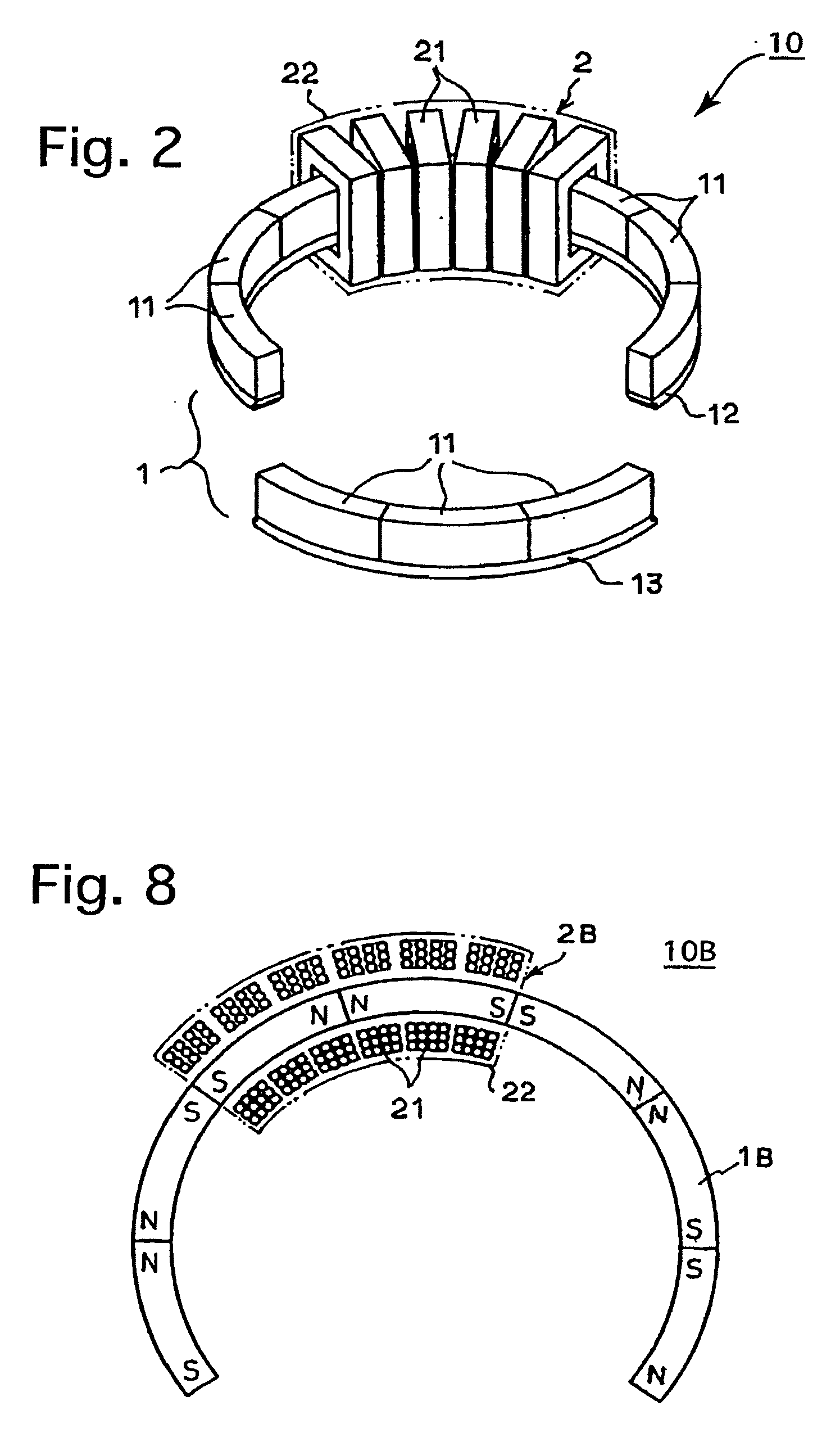
[0053]For instance, as shown in FIG. 8 that shows a third embodiment of a rotary actuator 10B, a multi-polar magnet 1B of the rotary actuator 10B is formed into an arc shape (C-shape) and does not form a complete circle, so that the coil body 2B reciprocally moves only within the range of the multi-polar magnet 1B in the circu...


PUM


Abstract

A rotary actuator includes a multi-polar magnet, in which north and south poles are alternately arranged in a circumferential direction, the multi-polar magnet being shaped into one of a circular ring and a circular arc member; and a coil body having coils which are provided around the multi-polar magnet to be capable of moving in the circumferential direction of the multi-polar magnet, each of the coils substantially lying on a plane that extends in a radial direction of the multi-polar magnet and orthogonal to the circumferential direction of the multi-polar magnet. The north and south poles of the multi-polar magnet are positioned apart from each other by a predetermined interval in the circumferential direction. Dimensions of each coil are predetermined so that length of each coil in the circumferential direction is associated with the predetermined interval. Predetermined currents are passed through the coils in a properly phased manner.

Description

BACKGROUND OF THE INVENTION[0001]1. Field of the Invention[0002]The present invention relates to a rotary actuator which is composed of at least one magnet and at least one coil body and which performs a rotation operation with the use of magnetic force, and in particular relates to a rotary actuator which is incorporated in a camera lens and suitable for use as a drive source for an autofocus mechanism.[0003]2. Description of the Related Art[0004]DC motors are generally used as actuators for performing a rotation operation with the use of magnetic force. For instance, a DC motor is incorporated in an SLR camera lens to be used as a drive source for performing a lens driving operation when autofocus (AF) control is performed. For example, in Japanese Unexamined Patent Publication Nos. 2006-259113 and 2006-145783, a DC motor is incorporated in a camera body and another DC motor is incorporated in a photographic lens, and appropriate AF control is performed by appropriately switching ...

Claims


Application Information

Patent Timeline
Patent Type & Authority Applications(United States)
IPC IPC(8): G02B7/10H02K21/14
CPCG03B19/12H02K21/12G03B3/10H02K41/03H02K2201/15H02K21/26
Inventor KUROSAWA, YUICHI
Owner RICOH IMAGING COMPANY
Why Eureka
Try Eureka