Adapter connection structure

a technology of adapter and connection structure, which is applied in the direction of coupling device connection, vessel construction, marine propulsion, etc., can solve the problems of increasing cost, and achieve the effect of minimizing transmission loss, minimizing the length of dc power cable, and reducing cos

Active Publication Date: 2009-12-31
SPI ELECTRONICS
View PDF13 Cites 6 Cited by
  • Summary
  • Abstract
  • Description
  • Claims
  • Application Information

AI Technical Summary

Benefits of technology

[0007]The adapter comprises a first converter and a second converter. The first converter receives an input power via an input terminal and converts the input power into a transitional power. The transitional power is transmitted from the first converter to the second converter via a transit cable. The second converter converts the transitional power into a DC output power. The DC output power is output via a DC power cable. The second converter is arranged to adjoin the output terminal as much as possible to minimize the length of the DC power cable and then minimize the transmission loss. The first converter converts the input power into a transitional power, and the transitional power may be a high-voltage and high-frequency AC power or a high-voltage DC power. The high-voltage and high-frequency transitional power will be converted into a rated output DC power by the second converter. Because of high frequency and high voltage, the transitional power has less transmission loss in the transit cable. Thereby, not only transmission loss is decreased, but also the cable can adopt a less expensive one. Therefore, the entire cost of buying and using an adapter is reduced.

Problems solved by technology

However, only a larger-size device, such as a personal computer or a further lager system, has a built-in power supply device.
Then, the cost is increased.

Method used


Image

  • Adapter connection structure
  • Adapter connection structure
  • Adapter connection structure

Examples


second embodiment

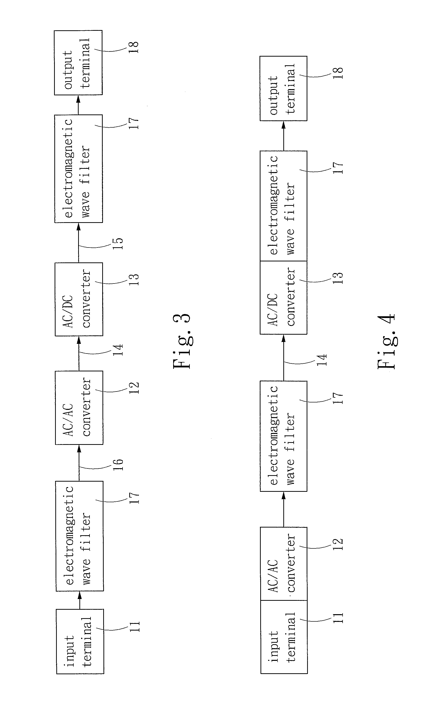
[0021]Refer to FIG. 7 is a perspective view of the second embodiment shown in FIG. 4, wherein the AC / AC converter 12 and the input terminal 11 are integrated into a one-piece component having a plug-like appearance, and the AC / DC converter 13 and the electromagnetic wave filter 17 are also integrated into a one-piece component. The AC / AC converter 12 receives the input power and converts the input power into the transitional power and transmits the transitional power to the AC / DC converter 13 via the electromagnetic wave filter 17 and the transit cable 14. Then, the AC / DC converter 13 generates the DC output power.

fifth embodiment

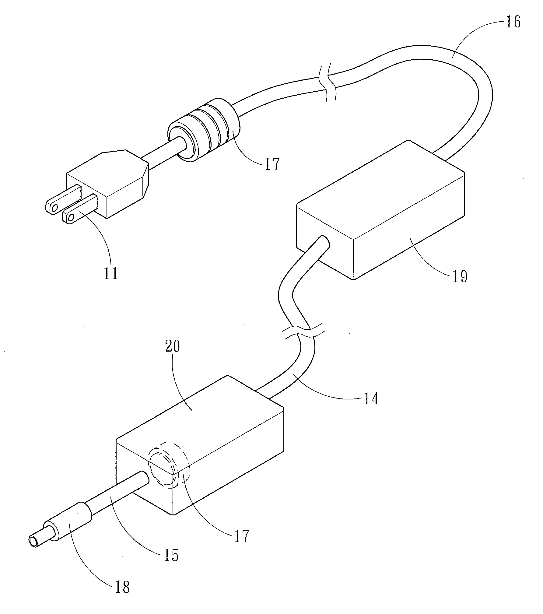
[0022]Refer to FIG. 8 and FIG. 9 are respectively a perspective view and a block diagram of a fifth embodiment extended from the abovementioned embodiments. In this embodiment, the AC / DC converter 19 functioning as the first converter also receives the input power from the input terminal 11 and converts the input power into the transitional power and transmits the transitional power to the second converter via the transit cable 14. In this embodiment, the DC / DC converter 20 functions as the second converter and is integrated with the electromagnetic wave filter 17 to form a one-piece component. The DC / DC converter 20 is arranged to adjoin the output terminal 18 as much as possible to shorten the DC power cable 15 and reduce the transmission loss in the DC power cable 15.

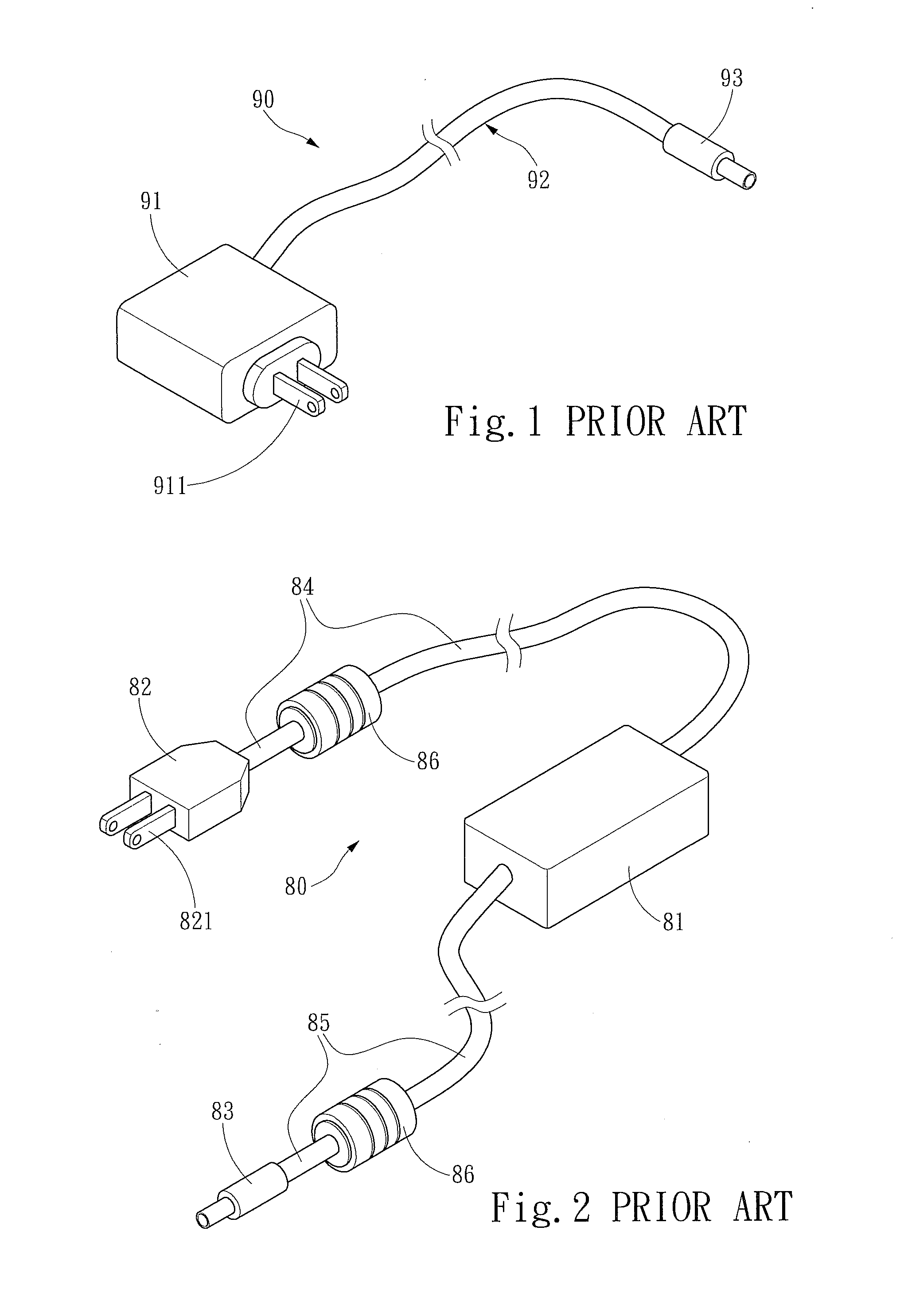
[0023]The structure of the present invention is distinct from the conventional adapters in that the structure of the present invention comprises the first converter and the second converter, which are separated from ...


PUM


Abstract

The present invention discloses an adapter connection structure, which comprises a first converter and a second converter. The first converter is connected to at least one input terminal to receive an input power and converts the input power into a transitional power. The second converter is connected to the first converter via a transit cable to transmit the transitional power, converts the transitional power into a DC output power and outputs the DC output power via a DC power cable. As the transitional power transmitted from the first converter to the second converter is in form of a high-voltage and high-frequency AC power or a high-voltage DC power, the power transmission loss in the transit cable is reduced. Therefore, the present invention not only can reduce transmission loss but also can adopt a less expensive cable. Thus is reduced the total cost of buying and using the adapter.

Description

FIELD OF THE INVENTION[0001]The present invention relates to an adapter connection structure, particularly to an improved architecture and connection relationship of an adapter providing power to drive the electronic device.BACKGROUND OF THE INVENTION[0002]Most of electronic devices need stable power supply. However, only a larger-size device, such as a personal computer or a further lager system, has a built-in power supply device. A smaller-size device or a portable device needs an adapter to receive power. One end of the adapter is connected to a city power, and the other end is connected to a connector to output a DC (Direct Current) power.[0003]Refer to FIG. 1 for a conventional adapter 90, which may be a mobile phone charger or a DC power plug for a small-size electric appliance. The adapter 90 comprises an AC / DC converter 91 and a DC power cable 92. The AC / DC converter 91 has at least one conduction terminals 911. The AC / DC converter 91 receives an AC (Alternating Current) po...

Claims


Application Information

Patent Timeline
Patent Type & Authority Applications(United States)
IPC IPC(8): H02M1/00
CPCH01R13/719H02M2001/007H02M7/217H01R31/065H02M1/007
Inventor XU, MING
Owner SPI ELECTRONICS
Why Eureka
Try Eureka