Containment vessel and nuclear power plant therewith

a technology for containment vessels and nuclear power plants, applied in nuclear engineering problems, nuclear elements, greenhouse gas reduction, etc., can solve the problems of inability to intake steam, containment may be irrational, and nitrogen-based non-condensable gases cannot be condensed,

Inactive Publication Date: 2009-12-31
KK TOSHIBA
View PDF29 Cites 27 Cited by
  • Summary
  • Abstract
  • Description
  • Claims
  • Application Information

AI Technical Summary

Benefits of technology

[0033]FIG. 1 is a vertical cross sectional view of a containment vessel according to a first embodiment of the present invention;
[0034]FIG. 2 is a graph showing the pressure changes in case of a LOCA according to this embodiment;
[0035]FIG. 3 is a vertical cross sectional view of a containment vessel according to a second embodiment of the present invention;
[0036]FIG. 4 is

Problems solved by technology

The suppression pool water condenses all steam in the gas, but noncondensable gas such as nitrogen cannot be condensed.
Thus, the containment may be irrationally designed as if it had two large dry wells practically.
Without this function, although the PCCS heat exchanger can initially condense the steam efficiently, noncondensable gases such as hydrogen and nitrogen would be stagnant in the PCCS heat exchanger and it would immediately become unable

Method used


Image

  • Containment vessel and nuclear power plant therewith
  • Containment vessel and nuclear power plant therewith
  • Containment vessel and nuclear power plant therewith

Examples


first embodiment

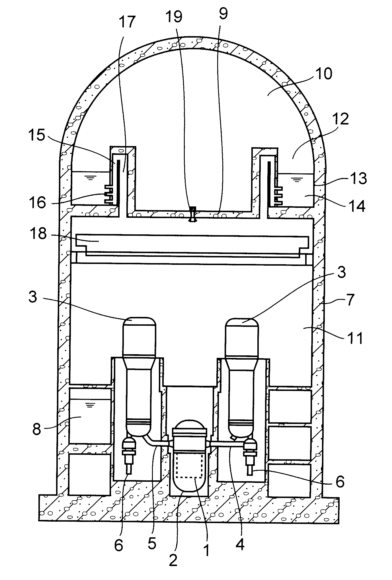
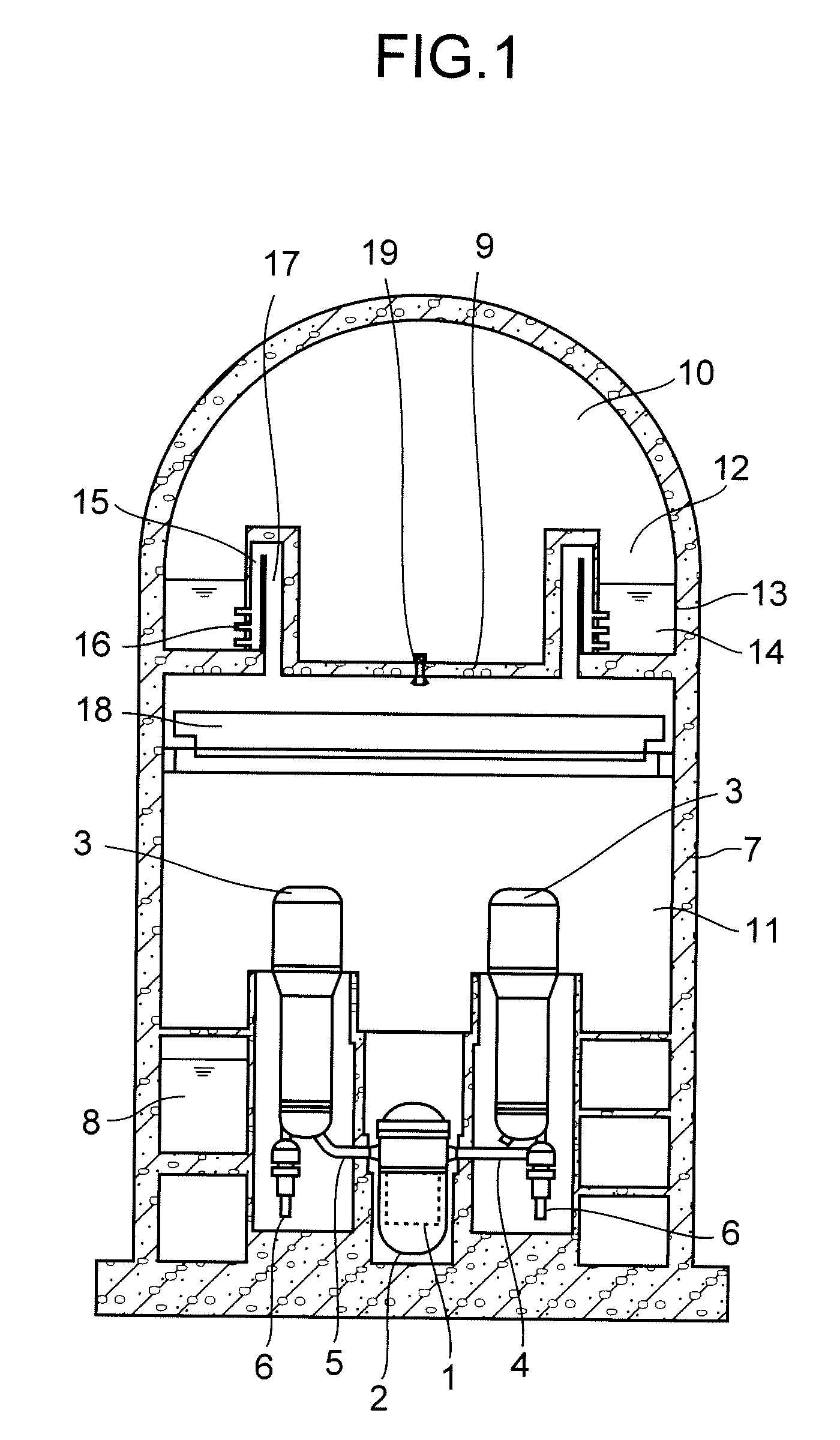
[0041]FIG. 1 is a vertical cross sectional view of a containment vessel according to a first embodiment of the present invention.

[0042]A nuclear power plant having a pressurized water reactor has a reactor core 1 and a reactor pressure vessel 2 containing the reactor core 1. The reactor pressure vessel 2 is connected to, for example, two steam generators 3 with both cold leg pipe 4 and hot leg pipe 5. A reactor coolant pump 6 that circulates a reactor coolant through the reactor core 1 and the steam generators 3 is attached directly to a bottom of the steam generators 3, for example. These equipment and piping constitute a reactor pressure boundary. The containment vessel of the pressurized water reactor contains the equipment and piping constituting the reactor pressure boundary.

[0043]The containment vessel according to this embodiment has a main containment vessel (MCV) 7 and a diaphragm 9. The main containment vessel 7 is made of reinforced concrete and is composed of a flat disk...

second embodiment

[0065]FIG. 3 is a vertical cross sectional view of a containment vessel according to a second embodiment of the present invention.

[0066]The containment vessel according to this embodiment is provided with a passive containment cooling system building (PCCS) 20 outside the main containment vessel 7 for installing a passive containment cooling system 21. The passive containment cooling system 21 has a PCCS pool 22 provided in the PCCS building 20 and a PCCS heat exchanger 24. The PCCS pool 22 is configured to store PCCS pool water 23. The PCCS heat exchanger 24 is placed to be submerged in the PCCS pool water 23. The PCCS heat exchanger 24 is connected to a suction pipe 25 of which end opens to the lower vessel 11. The PCCS heat exchanger 24 is also connected to a return pipe 26 that returns the condensed water back into the lower vessel 11. Further, a PCCS vent pipe 27 through which the noncondensable gas that is not condensed in the PCCS heat exchanger 24 to the upper vessel 10 is p...

third embodiment

[0075]FIG. 4 is a vertical cross sectional view of a containment vessel according to a third embodiment of the present invention.

[0076]In the containment vessel according to this embodiment, the pressure suppression chamber 12 is provided in the lower vessel 11. The pressure suppression chamber 12 is positioned so that the level of the suppression pool water 14 stored in the suppression pool 13 is higher than the cold leg pipe 4. The aim that it is positioned higher than the cold leg piping pipe is to use the suppression pool water 14 as water source for the gravity-driven cooling system so that the water may flow into the reactor pressure vessel 2 by the gravity.

[0077]A gas phase vent pipe 29 connects the gas phase of the pressure suppression chamber 12 to the upper vessel 10. In this embodiment, the gas phase vent pipe 29 is embedded in the wall of the main containment vessel 7 to achieve high efficiency of arrangement, however, the gas phase vent pipe 29 may extend inside or outs...


PUM


Abstract

A containment vessel for containing a reactor pressure vessel and steam generators has a main containment vessel, a diaphragm, a pressure suppression chamber, LOCA vent pipes. The reactor pressure vessel contains a reactor core of a pressurized water reactor. The diaphragm partitions the main containment vessel into an upper vessel and a lower vessel. The pressure suppression chamber has a suppression pool to store water and gas phase of the pressure suppression chamber communicates with the upper vessel. The LOCA vent pipes connect the pressure suppression chamber to the lower vessel. All of the equipments and piping that constitute the reactor pressure boundary, including the reactor pressure vessel, the steam generators, a cold leg pipe and a hot leg pipe, are contained in the lower vessel.

Description

CROSS REFERENCE TO RELATED APPLICATION[0001]This application is based upon and claims the benefit of priority from the prior Japanese Patent Application No. 2007-330918 filed on Dec. 21, 2007; the entire content of which is incorporated herein by reference.BACKGROUND OF THE INVENTION[0002]The present invention relates to a containment vessel of a pressurized water reactor and to a nuclear power plant therewith.[0003]Most light water reactors (LWRs) have a safety system such as an emergency core cooling system (ECCS). Reactors having an active component such as a pump are called “active safety reactors”. On the other hand, reactors with a safety system that has a passive component such as a tank are called “passive safety reactors”.[0004]Known as a passive safety reactor representing boiling water reactors (BWRs) is the natural circulation cooling type passive safety BWR (ESBWR) (see, for example, IAEA-TECDOC-1391, “Status of advanced light water reactor design 2004,” IAEA, May 2004,...

Claims


Application Information

Patent Timeline
IPC IPC(8): G21C9/004
CPCG21C13/00G21C15/18Y02E30/32G21Y2004/30G21Y2002/304Y02E30/30G21C9/004
Inventor SATO, TAKASHIOTONARI, JUNICHIROFUJIKI, YASUNOBUMIYAGAWA, TAKUYASATO, HISAKI
Owner KK TOSHIBA
Why Eureka
Try Eureka