
Emitter tracking system

a technology of emitter tracking and tracking system, which is applied in the direction of image enhancement, direction controller, instruments, etc., can solve the problems of a number of shortcomings of existing beacon tracking systems, as well as those relying on them, and achieve the effect of increasing the signal-to-noise ratio of captured images

Inactive Publication Date: 2009-12-31
FLIR SYST INC
View PDF14 Cites 25 Cited by
  • Summary
  • Abstract
  • Description
  • Claims
  • Application Information

AI Technical Summary

Benefits of technology

[0002]Satellites, missiles, and other self-propelled or independently propagating devices often are tracked remotely for various purposes. For example, in the case of a communications satellite, it may be desirable to send and receive narrow directional signals to and from the satellite, and, to do so efficiently, the position of the satellite must be known with precision. Similarly, in the case of a global-positioning satellite, the position of the satellite must be known precisely if it is to serve its purpose as a precision locator of ground-based objects. In the case of a guided missile, such as a tube-launched, optically tracked, wire-guided (TOW) missile, knowing the position of the missile precisely may allow desirable in-flight course corrections.
[0003]To facilitate precision measurements of the position of objects such as those described above, the object may be equipped with a beacon that emits a signal having known properties. Using these properties, a “signal detection system” or non-imaging system may be configured to detect the particular signature of the beacon, and to activate an imaging system to determine the position of the beacon with a desired amount of precision. The position information obtained in this manner may be used to direct signals to and / or from the moving object, to correct the trajectory of the object as needed, and / or for any other purpose. Furthermore, the imaging system employed for tracking also may be used to obtain more general images of the moving object and its surroundings, such as images of an intended target area. This can provide desirable situational awareness beyond mere tracking information.
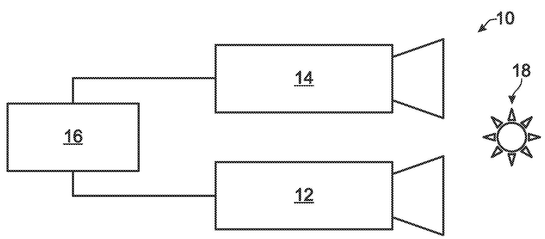
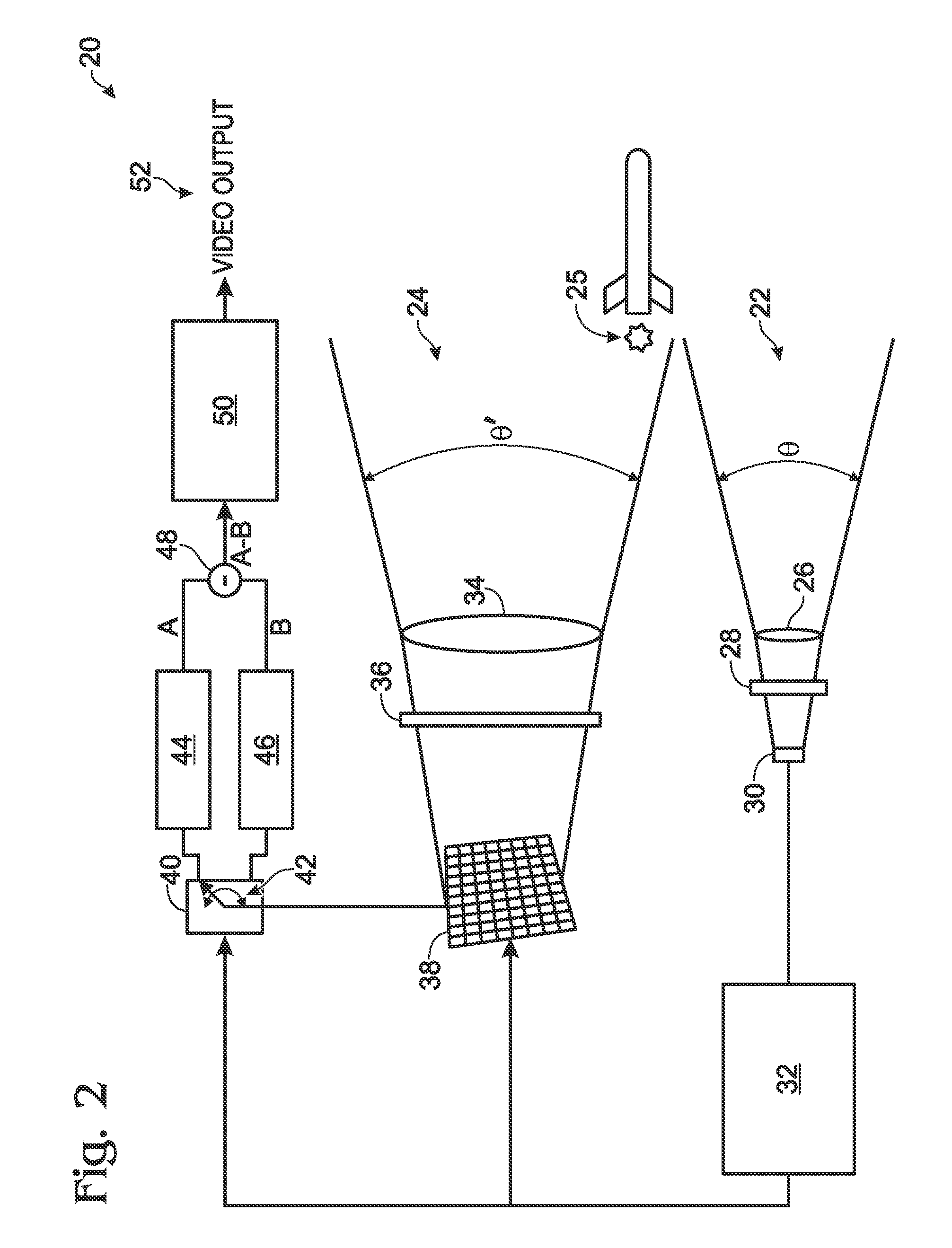
[0005]The present disclosure relates to an improved emitter tracking system. In aspects of the present teachings, the presence of a desired emitter may be established by a relatively low-power emitter detection module, before images of the emitter and / or its surroundings are captured with a relatively high-power imaging module. Capturing images of the emitter may be synchronized with flashes of the emitter, to increase the signal-to-noise ratio of the captured images.

Problems solved by technology

However, existing beacon tracking systems, such as the system of Wells et al., as well as those relying on various scanning techniques, may suffer from a number of shortcomings.
These include, for example, poor image quality, inherent latencies leading to time-delayed images, relatively high power consumption, and / or moving parts that may require maintenance and / or have a propensity for malfunction.

Method used


Image

  • Emitter tracking system
  • Emitter tracking system
  • Emitter tracking system

Examples


example 1

[0032]This example relates to and further describes emitter tracking incorporating image subtraction, according to aspects of the present teachings. As described previously, once the presence and characteristic signal of an emitter has been detected, a processor may electronically subtract an emitter-off image from an emitter-on image, to eliminate background image noise and to improve the signal-to-noise ratio of the resultant subtracted image. The simplest way to accomplish this is for the imaging module to capture a single one-half period of the emitter signal for each image, corresponding to capturing one image with the emitter on, and one with the emitter off. Subtracting the emitter-off image from the emitter-on image results in an image of the emitter with relatively little background noise.

[0033]Alternatively, the system could be configured to capture and integrate multiple emitter-on and emitter-off images. For example, the imaging module could capture and integrate a compo...

example 2

[0034]This example relates to and further describes emitter tracking incorporating coded emitters, according to aspects of the present teachings. As described previously, an emitter signal may be coded to contain information about the signal emitter and / or to facilitate positively identifying the signature of a particular emitter. When an emitter tracking system seeks to track a coded emitter, the system may perform several steps in conjunction with, or prior to, capturing image data for display or tracking purposes. First, an emitter tracking system according to the present teachings may perform the preliminary step of extracting the emitter “pulse rate” or “clock” from the received emitter signal. Because this signal may, for example, include missing pulses and / or have an irregular frequency, characterizing the received signal with a processor may be necessary or desirable.

[0035]Once an incoming emitter signal has been received and characterized with a “pulse rate” or other defini...

example 3

[0036]This example relates to and further describes exemplary methods of tracking an emitter, according to aspects of the present teachings.

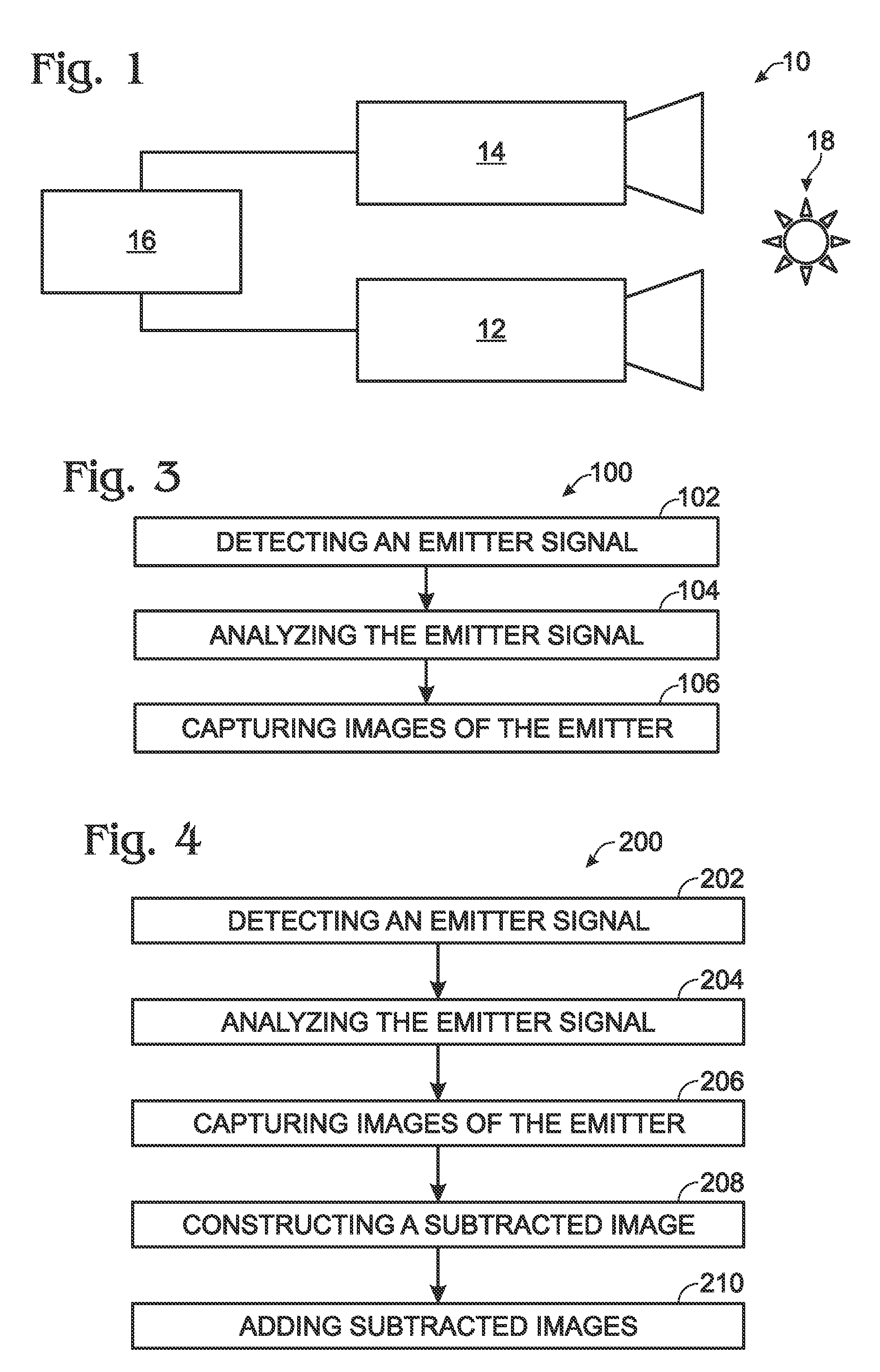
[0037]FIG. 3 is a flowchart depicting a first exemplary method, generally indicated at 100, of tracking an emitter according to aspects of the present teachings. Method 100 generally includes a step 102 of detecting an emitter signal, a step 104 of analyzing the signal to determine if the signal includes a signature corresponding to a particular emitter, and a step 106 of capturing images of the emitter. Generally, step 106 will be performed only if the detected emitter signal includes the desired signature, so that the power and other resources associated with capturing images need not be expended unless a desired emitter, which may be one of a predefined set, has been positively identified.

[0038]Detecting an emitter signal may be performed with a signal detection module, analyzing the detected signal may be performed with a processor, and capt...


PUM


Abstract

An improved emitter tracking system. In aspects of the present teachings, the presence of a desired emitter may be established by a relatively low-power emitter detection module, before images of the emitter and / or its surroundings are captured with a relatively high-power imaging module. Capturing images of the emitter may be synchronized with flashes of the emitter, to increase the signal-to-noise ratio of the captured images.

Description

CROSS-REFERENCE[0001]This application is based upon and claims the benefit under 35 U.S.C. §119(e) of U.S. Provisional Patent Application Ser. No. 61 / 076,049, filed Jun. 26, 2008, which is incorporated herein by reference in its entirety for all purposes.INTRODUCTION[0002]Satellites, missiles, and other self-propelled or independently propagating devices often are tracked remotely for various purposes. For example, in the case of a communications satellite, it may be desirable to send and receive narrow directional signals to and from the satellite, and, to do so efficiently, the position of the satellite must be known with precision. Similarly, in the case of a global-positioning satellite, the position of the satellite must be known precisely if it is to serve its purpose as a precision locator of ground-based objects. In the case of a guided missile, such as a tube-launched, optically tracked, wire-guided (TOW) missile, knowing the position of the missile precisely may allow desi...

Claims


Application Information

Patent Timeline
Patent Type & Authority Applications(United States)
IPC IPC(8): G06K9/00
CPCF41G7/303F41G7/32G06T2207/30212G06T7/20G06T5/50G06V20/10F41G7/00
Inventor WAY, SCOTTARCHER, CYNTHIA I.
Owner FLIR SYST INC
Learn More