System and method for substrate transport

Active Publication Date: 2009-12-31
INTEVAC
View PDF42 Cites 17 Cited by
  • Summary
  • Abstract
  • Description
  • Claims
  • Application Information

AI Technical Summary

Benefits of technology

[0012]According to one aspect of the invention, conventional cassettes are used to transfer plurality of substrates in an atmospheric environment. Multiple-substrate carriers are used to each move a fraction or a subset of the substrates, e.g., five or six substrates, from the cassettes in an atmospheric environment into vacuum environment. Then, single or dual-substrate carriers are used to each transfer one or two substrates among the processing chambers. Once processing is completed, the reverse process takes place, i.e., multiple-substrate carriers are used to move fraction / subsets of substrates from vacuum to atmospheric environment, and then several subsets are placed together into one cassette. The use of multiple-substrate carriers to transfer a reduced number of substrates at once from atmospheric to vacuum environment allows for constructing a relatively small vacuum lock chambers, which allows for relatively slow vent and pump of the vacuum locks since the space needed to be evacuated is rather small. Additionally, it allows for the use of relatively slow actuating load lock valves, which reduces particles and increases meantime between failures and meantime between services. Moreover, since the multi-substrate carriers spend a relatively short time in atmospheric environment, they have little time to absorb water vapor, so that the amount of vapor entering the loadlock system in each cycle is very small and can be easily pumped out.

Problems solved by technology

As can be understood, having the cassettes travel into a vacuum environment necessitates a rather large gate valve and either a large pump or long pumping period, which slows the system.
Such particles can introduce unwanted defects.
Moreover, the secondary chamber housing the two robots and the buffer station must be constructed to be rather large, which requires long pumping time to maintain vacuum environment.
The prior art systems suffer from the problem of synchronizing transport time, vacuum pumping time, and process time.
However, transporting the substrate and pumping the chamber into a vacuum environment may take considerable time, such that it slows the throughput of the entire system.

Method used


Image

  • System and method for substrate transport
  • System and method for substrate transport
  • System and method for substrate transport

Examples


Embodiment Construction

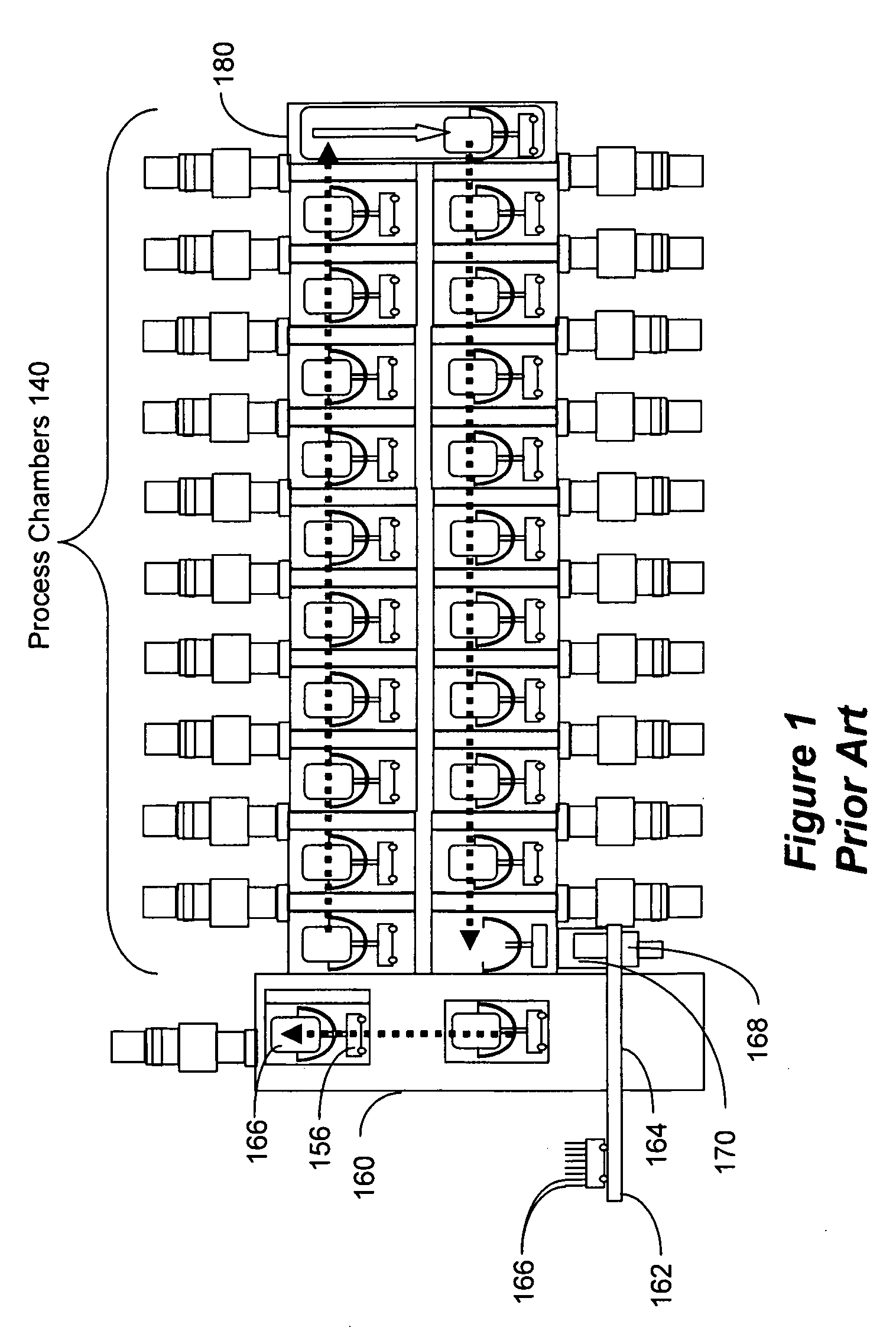
[0024]A detailed description will now be given of embodiments of the invention for introducing substrates into vacuum environment of a substrate processing system. FIG. 3 is a simplified schematic illustrating a processing system in accordance with an embodiment of the invention. The system of FIG. 3 includes a plurality of processing chambers 340 arranged linearly and stacked one row above the other. A carrier elevator 380 is provided at the end of the stacked processing chambers. At the front of the stacked chambers are front end module 360 and substrate loading module 370. Front end module 360 has tracks 364 upon which cassettes 362 are transported in atmospheric environment, so as to deliver substrates 366 to the system. However, unlike the prior art system of FIG. 1, this embodiment further includes buffer module 390. Buffer module 390 includes a series of vacuum locks—here only two are shown, i.e., 392 and 394, but the number of vacuum locks can be changes as necessary. Multi-...


PUM


Abstract

Introduction of substrates into vacuum environment is accomplish by gradually reducing the number of substrates being transferred simultaneously as the clean and evacuated environment is progressed. Cassettes are maintained in clean atmospheric environment and do not enter the vacuum environment. Several vacuum locks are linearly staggered so as to introduce progressively higher level of vacuum environment. The number of substrates transported through this arrangement is a portion of the number of substrates present in each cassette. The staggered vacuum locks lead to a series of processing chambers, wherein a yet smaller number of substrates, e.g., one or two, are transported.

Description

RELATED APPLICATIONS[0001]This application claims priority benefit from U.S. provisional applications Ser. Nos. 61 / 077,067 and 61 / 084,600, filed on Jun. 30, 2008 and Jul. 29, 2008, respectively, the entire disclosure of which is incorporated herein by reference.BACKGROUND[0002]1. Field[0003]The subject invention relates to transporting of substrates for processing in a vacuum processing environment.[0004]2. Related Art[0005]Vacuum processing systems are used to fabricate hard-drive disks, semiconductor computer chips, solar panels, and the like, from substrates made of materials such as semiconductor wafers, glass, stainless steel, etc. Typically, the vacuum processing systems include several substrate chambers that perform various processes that modify the substrate by performing deposition, cleaning, etching, heating / cooling, etc., on the substrate The substrates are generally transported to the processing systems in cassettes holding several substrates in a clean atmospheric envi...

Claims


Application Information

Patent Timeline
IPC IPC(8): H01L21/677
CPCH01L21/67173H01L21/67313Y10S414/14H01L21/67781H01L21/67775
Inventor SCOLLAY, STUARTBLUCK, TERRYCHEN, XIANG
Owner INTEVAC
Why Eureka
Try Eureka