Friction-Welded Assembly with Interlocking Feature and Method for Forming the Assembly

a technology of interlocking feature and friction welding, which is applied in the direction of manufacturing tools, transportation and packaging, other domestic articles, etc., can solve the problems that the bonding strength and long-term durability of the weld joint formed via a conventional spin-welding process may be less than optimal

Active Publication Date: 2009-12-31
GM GLOBAL TECH OPERATIONS LLC
View PDF15 Cites 16 Cited by
  • Summary
  • Abstract
  • Description
  • Claims
  • Application Information

AI Technical Summary

Benefits of technology

[0005]When one of the components is rotated with respect to the other in the presence of an applied axial force, the components melt at or around the weld zone or interface, with molten flash flowing away from the weld zone and underneath the annular shelf. When the molten flash ultimately cools in the form of a flow pattern, a first interlocking feature is formed between the annular shelf and the flow pattern. The interlocking feature retains the components in at least one direction, thus optimizing the overall strength and / or durability of the welded assembly.
[0007]A method for forming a weld joint between a cylinder and a disc using a spin-welding process includes providing the disc with a circumferential undercut or groove forming an annular shelf, then rotating the cylinder with respect to the disc under a first axial compressive force during the spin-welding process. An outflow of molten flash is formed, which moves at least partially into the groove and under the annular shelf. The molten flash is then cooled to form a flow pattern, thus providing a first interlocking feature between the annular shelf of the disc and the flow pattern, which is suitable for preventing axial motion of the cylinder with respect to the disc independently of the weld joint.

Problems solved by technology

However, the bonding strength and long term durability of a weld joint formed via a conventional spin-welding process may be less than optimal when used in conjunction with certain applications, and therefore the spin-welding process is generally restricted or limited to welding relatively small cylindrical parts of similar or like material in order to maximize the strength of the resultant weld joint.

Method used


Image

  • Friction-Welded Assembly with Interlocking Feature and Method for Forming the Assembly
  • Friction-Welded Assembly with Interlocking Feature and Method for Forming the Assembly
  • Friction-Welded Assembly with Interlocking Feature and Method for Forming the Assembly

Examples


Embodiment Construction

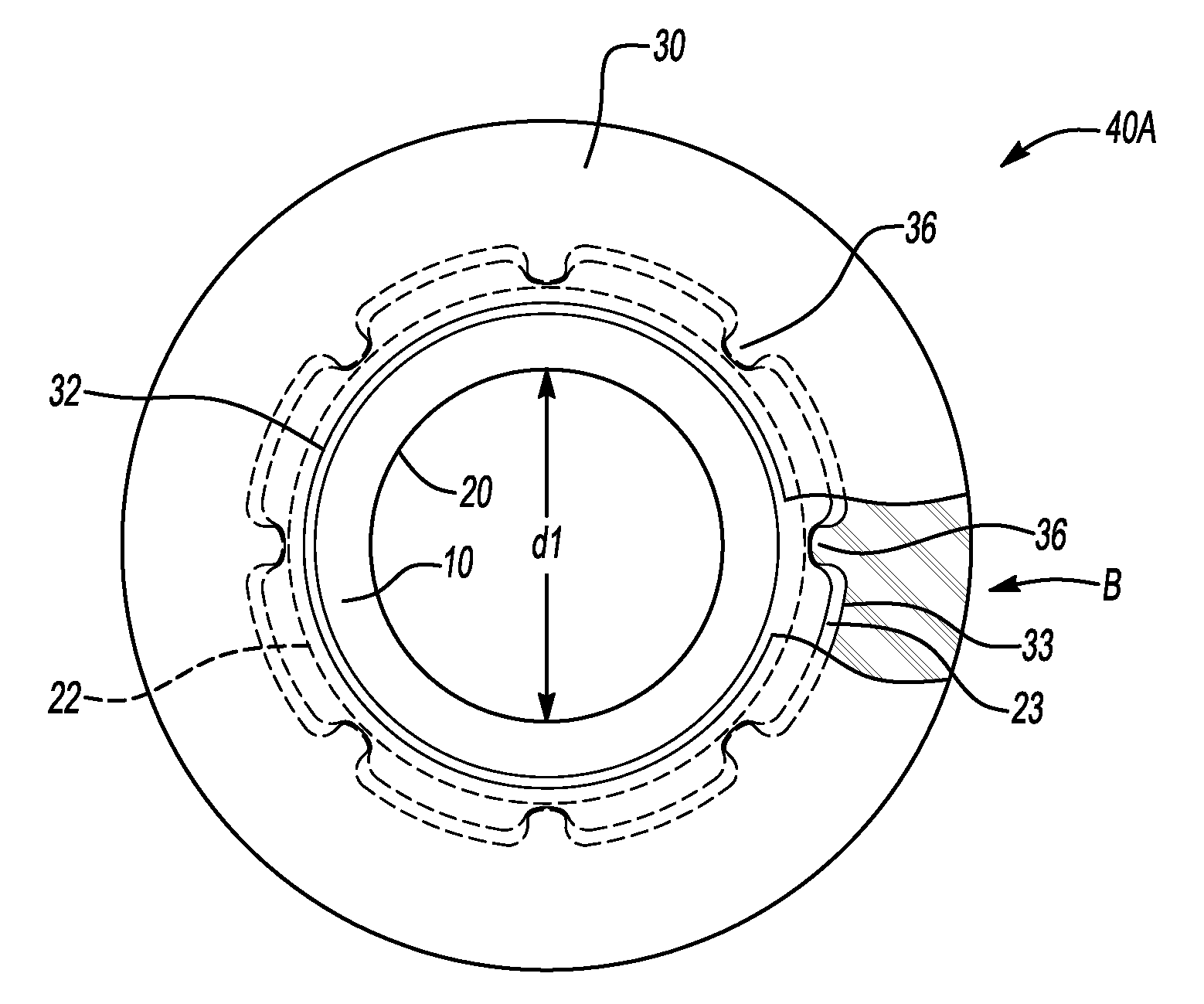
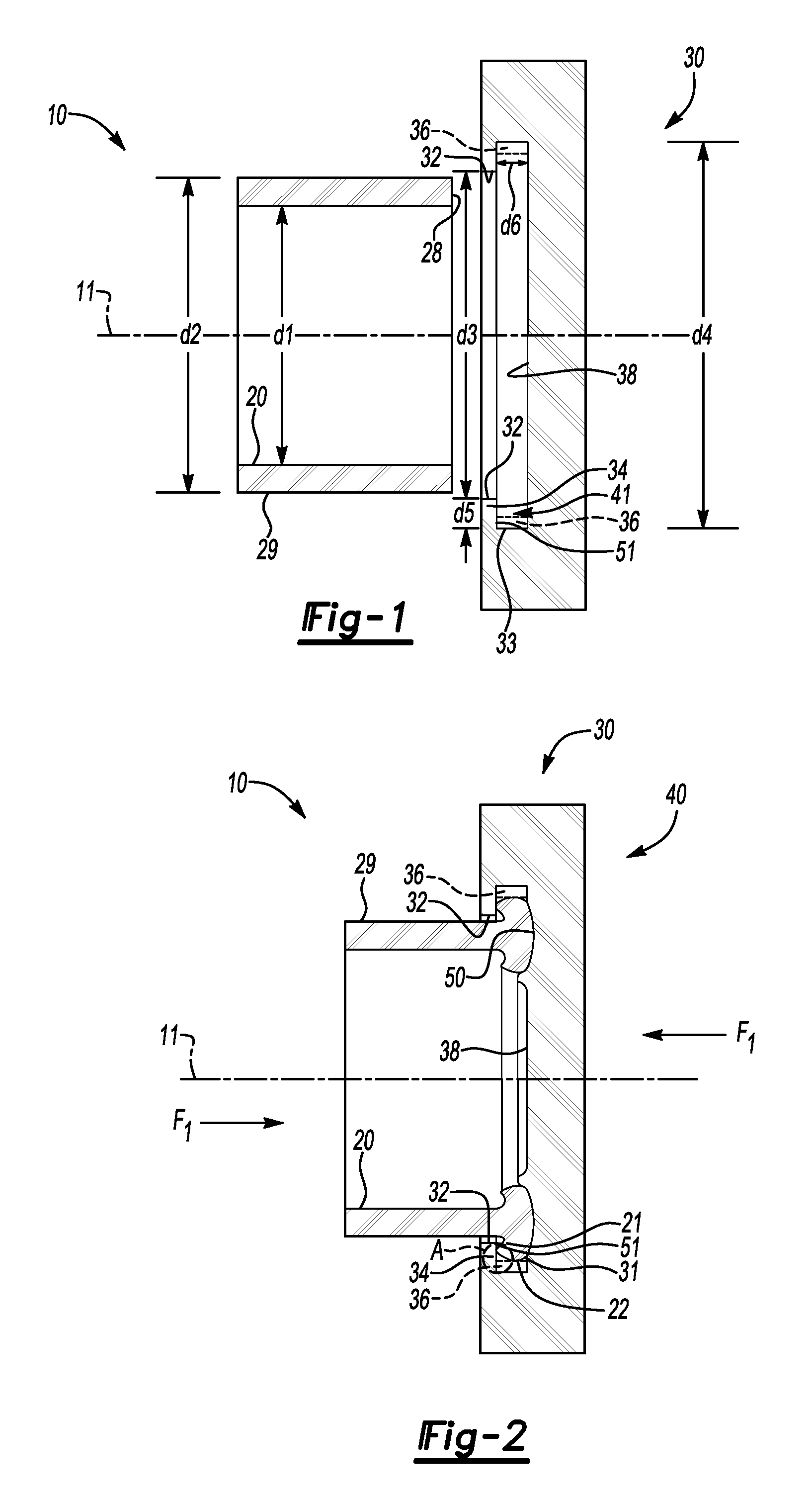
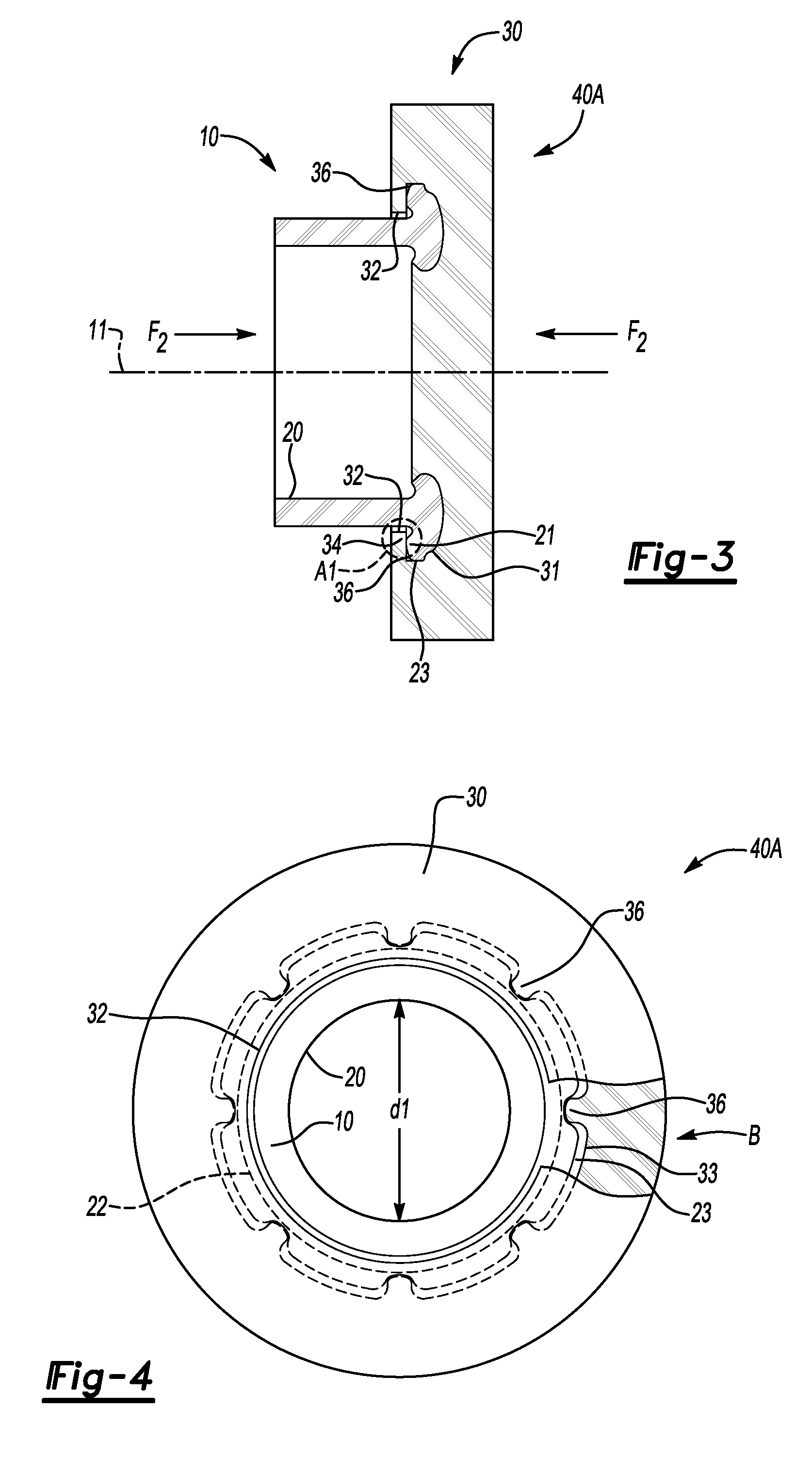
[0013]Referring to the drawings wherein like reference numbers represent like components throughout the several figures, and beginning with FIG. 1, a first component 10 and a second component 30 are shown as they appear prior to being subjected to a friction-welding or a spin-welding process in accordance with the invention, as will be described below. The first component 10 is shown in one embodiment as a tube or a cylinder, and the second component 30 is shown as a disc. As such a configuration is most typically used during a conventional spin-welding process, for simplicity the first and second components will be referred to respectively hereinafter as the cylinder 10 and the disc 30.

[0014]In one embodiment, the cylinder 10 and disc 30 are each constructed of the same or different types of suitable metal, such as an aluminum alloy, cast iron, or another suitable metal material. In another embodiment, the cylinder 10 and the disc 30 are each constructed of the same or different ty...


PUM

PropertyMeasurementUnit
axial forceaaaaaaaaaa
speedaaaaaaaaaa
axial compressive forceaaaaaaaaaa

Abstract

A welded assembly includes a weld joint formed via a spin-welding process. A disc receives a cylinder prior to spin-welding, with the disc having a circumferential groove undercutting or defining an annular shelf. An interlocking feature retaining the cylinder and disc is formed between a flow pattern of the cylinder and the annular shelf upon cooling of molten flash in the groove underneath the annular shelf. Teeth can be formed integrally with the disc to provide a torsional interlocking feature between the disc and cylinder. A method for forming a weld joint between a plastic cylinder and disc includes providing the disc with a circumferential groove forming an annular shelf, and rotating the cylinder with respect to the disc under an axial force to thereby form an outflow of molten flash. The flash forms an interlocking feature when cooled after flowing into the groove underneath the shelf.

Description

TECHNICAL FIELD[0001]The present invention relates to an optimized friction-welding method and assembly.BACKGROUND OF THE INVENTION[0002]In a friction-welding process, such as conventional spin-welding process, the components to be welded or fused are placed adjacently to each other and then rotated at a high relative rate of speed in conjunction with an applied axial clamping force. The frictional heating generated at or along a boundary or interface between the components melts a portion of the material, typically plastic or metal, which then flows away from the interface or the “weld zone” in molten form, hereinafter referred to as “molten flash”. When the molten flash cools, a homogenous weld joint is formed at or along the weld zone from the now intermixed materials of the welded components.[0003]Spin-welding provides many advantages, such as relatively short cycle times, large batch sizes, and high overall process efficiency. Spin-welding also provides excellent repeatability ...

Claims


Application Information

Patent Timeline
Patent Type & Authority Applications(United States)
IPC IPC(8): B32B15/02B23K20/12
CPCB23K20/12Y10T428/12326B23K33/006B23K2201/006B23K2201/06B23K2203/02B23K2203/10B29C65/0672B29C65/568B29C66/20B29C66/225B29C66/30325B29C66/322B29C66/712B29C66/83221B29K2101/12B23K20/129Y10T428/1352Y10T428/12757Y10T428/139Y10T428/13Y10T428/12292B29C66/5346B29C65/00B23K2101/006B23K2101/06B23K2103/02B23K2103/10B29C66/112B29C66/114B29C66/24221
Inventor KLEBER, RICHARD M.
Owner GM GLOBAL TECH OPERATIONS LLC
Why Eureka
Try Eureka