
Method for manufacturing a strip for use with a multi-input meter

a multi-input meter and strip technology, applied in the direction of instruments, material electrochemical variables, phase/state change investigation, etc., can solve the problems of multi-input meter backward compatibility with dual electrodes, not always necessary or desirable to use test strips, test strips, etc., to increase the current that flows through the electrodes, and the working surface of the electrodes is effectively enlarged.

Inactive Publication Date: 2009-12-31
LIFESCAN SCOTLAND
View PDF7 Cites 99 Cited by
  • Summary
  • Abstract
  • Description
  • Claims
  • Application Information

AI Technical Summary

Benefits of technology

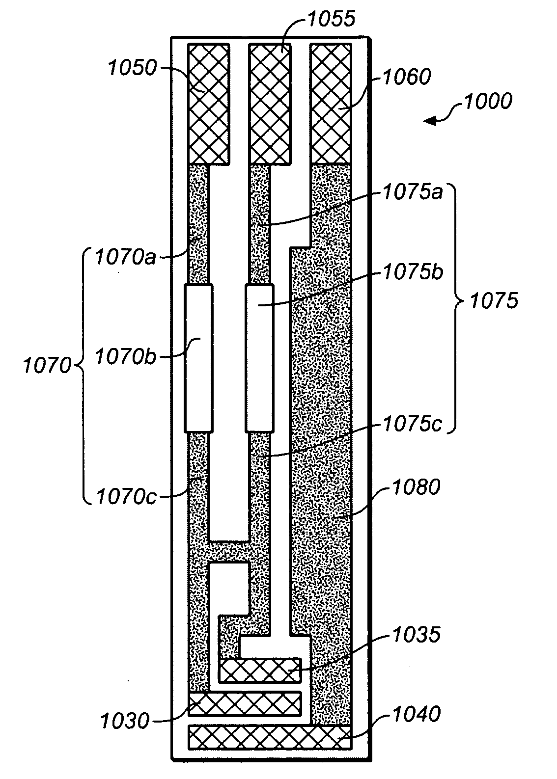
[0015]Coupling working electrodes to multiple working connectors enables a single working electrode (or a single group of interconnected working electrodes) to provide current to more than one of the working connectors (via the plurality of working links). On connection of the strip to a multi-input meter, the total current supplied by the electrodes will be split between the working links and therefore also between the connectors. Thus, the working electrode will appear to the meter to be a plurality of electrodes, with a different one of the plurality connected to each working connector. In this way, the strip enables a multi-input meter to be used with fewer working electrodes than are normally required by the meter.
[0031]The formation of split links as first and third link portions, separated by a gap with a second portion bridging the gap, facilitates the strips' manufacture. Large numbers of identical strip ‘blanks’ can be manufactured with only the first and third link portions in place, with the subsequent second link portion added at a later stage to bridge the first and third link portions, which can be accomplished by a suitable technique, such as, for example, by screen printing. Selecting materials of appropriate resistivities for the third link portions allows the easy customisation of a strip ‘blank’ into a strip adapted for a particular meter. Since this process of customisation is simply the overlaying of material to form the bridging second link portions, it is well suited for low-volume manufacturing methods.

Problems solved by technology

It is not always necessary or desirable to use test strips with more than one working electrode.
However, multi-input meters are often not backwards compatible with dual electrode (i.e. single reference electrode and single working electrode) test strips.
A multi-input meter with an unconnected second working sensor input may interpret lack of an input as an erroneous measurement and indicate an error in the test strip.
The restriction that a meter can only be used with particular test strips that have configurations that are matched to that meter is inconvenient to a user, who is consequently forced to use only those test strips.
Thus, a user who has recently replaced his existing single working sensor meter with a multi-input meter may find that his supply of single working electrode test strips for use with his previous meter are not compatible with the multi-input meter and must be discarded and replaced with new multiple sensor test strips.
Equally, a user may not always be able to obtain test strips that are designed specifically for his meter, although test strips designed for different meters may be available to him.
The provision of multiple working sensors on a test strip adds to the test strip's complexity and therefore also to the cost and difficulty of its manufacture.
It is also to be expected that manufacturing defects will be more common in test strips of greater complexity.
However, if a multi-input meter is used, the lack of backwards compatibility with single working sensor test strips forces the user to use the more complex multiple working sensor test strips, even if they are not required for his application.
Finally, the presence of multiple working sensors is problematic in cases where only a very limited quantity of sample material (e.g. blood) is available.
Therefore, the lack of compatibility between multi-input meters and single working electrode test strips inhibits the use of test strips that are better suited for certain applications.
This approach permits an otherwise inappropriately large current to be split between inputs that are configured to accept a lower current.

Method used


Image

  • Method for manufacturing a strip for use with a multi-input meter
  • Method for manufacturing a strip for use with a multi-input meter
  • Method for manufacturing a strip for use with a multi-input meter

Examples


Embodiment Construction

in conjunction with the accompanying drawings that are first briefly described.

BRIEF DESCRIPTION OF THE DRAWINGS

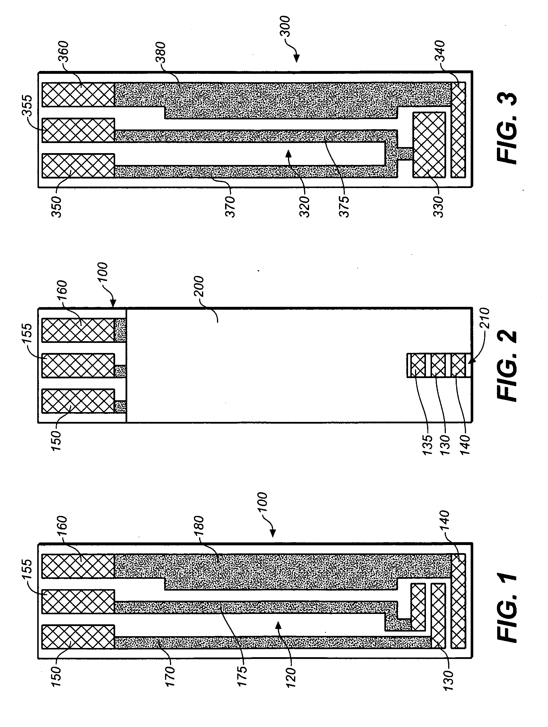
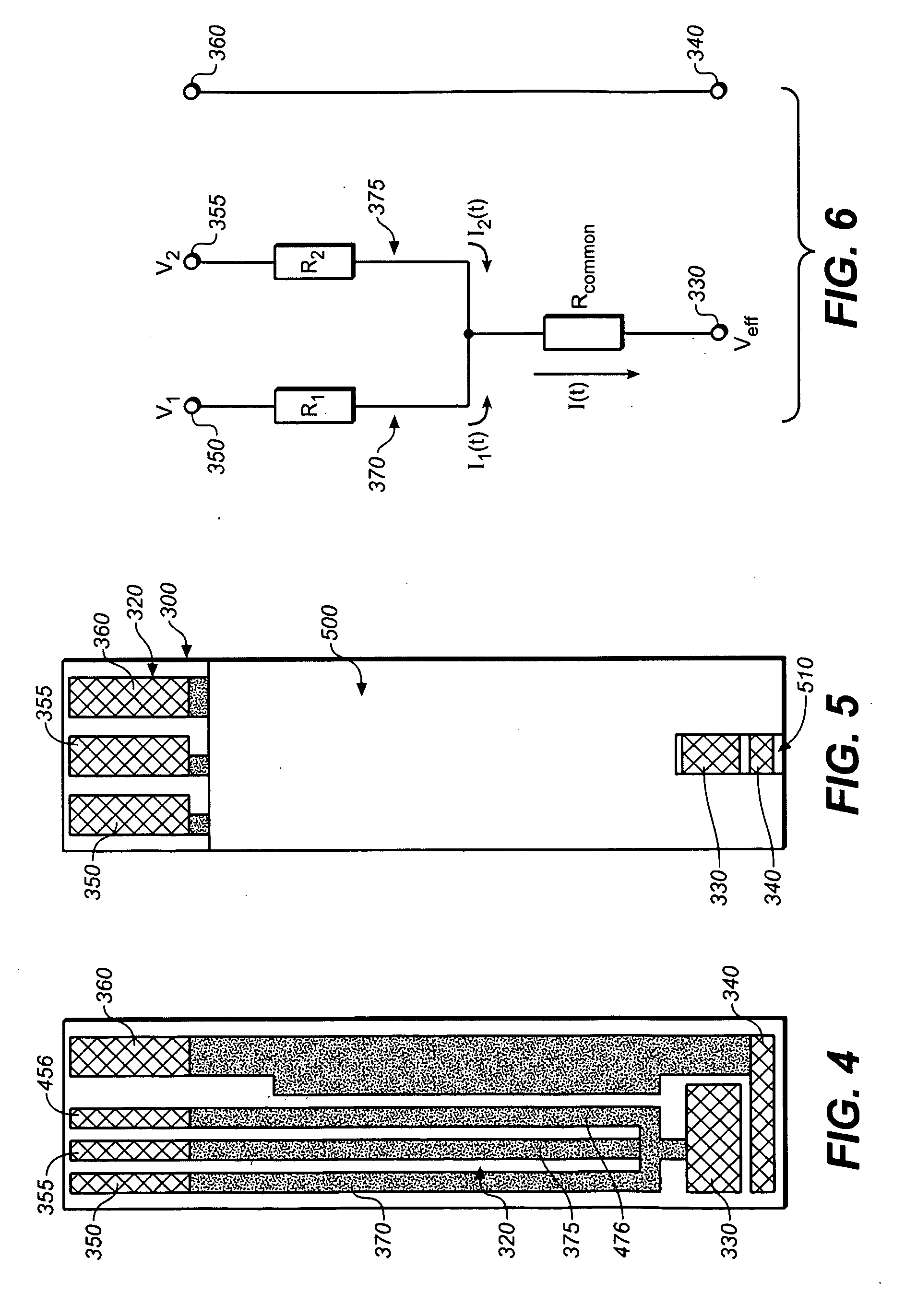
[0037]The accompanying drawings, which are incorporated herein and constitute part of this specification, illustrate presently preferred embodiments of the invention, and, together with the general description given above and the detailed description given below, serve to explain features of the invention (wherein like numerals represent like elements), of which:

[0038]FIG. 1 shows a prior art test strip having two working electrodes;

[0039]FIG. 2 shows the prior art test strip of FIG. 1 partially covered by a dielectric mask;

[0040]FIG. 3 shows a test strip according to a preferred embodiment having two working links and connectors;

[0041]FIG. 4 shows a test strip according to a preferred embodiment having three working links and connectors;

[0042]FIG. 5 shows the test strip of FIG. 3 covered by a dielectric mask;

[0043]FIG. 6 shows a circuit diagram of a portion of a test stri...


PUM

PropertyMeasurementUnit
polarizing voltageaaaaaaaaaa
electrochemical measurementaaaaaaaaaa
electrochemical testaaaaaaaaaa

Abstract

Strips particularly test strips and adapters for test strips, for use in meters for the electrochemical measurement of analyte in a sample material and in particular the glucose concentration of a sample of blood. The strips comprise a plurality of working connectors, for interfacing with the meter, coupled to one or more working electrodes. The strips are of particular use in adapting multi-input meters for single input use.

Description

FIELD OF THE INVENTION[0001]The present invention relates to strips for use with multi-input meters for the electrochemical measurement of analyte in a sample material. In particular, the invention relates to test strips and adapters for test strips for determining glucose concentration in samples of blood.BACKGROUND OF THE INVENTION[0002]Devices for measuring blood glucose levels are invaluable to diabetics—especially devices that may be used by the sufferers themselves, enabling them to monitor their own glucose levels and take doses of insulin.[0003]Conventionally, at least the part of the glucose-measuring device that comes into contact with the blood sample is disposable. This is important for reasons of hygiene, ease of use, the avoidance of cross-contamination between samples, and to prevent the spread of infectious diseases. Since diabetics must frequently check their glucose levels, it is important that the cost of the disposable is minimised.[0004]Current glucose measuring...

Claims


Application Information

Patent Timeline
Patent Type & Authority Applications(United States)
IPC IPC(8): G01N27/26H01R43/00
CPCY10T29/49117G01N27/3272
Inventor HAGGETT, BARRYBIRCH, BRIANANDRES, ROBERTOBASKEYFIELD, DAMIAN EDWARD HAYDON
Owner LIFESCAN SCOTLAND
Learn More