RF sensor system and method for operating the same

a sensor system and radio frequency technology, applied in the field of radio frequency (rf) sensor system, can solve the problems of serious power waste, unnecessarily increasing load of circuit, and reducing the efficiency of hardware resources, so as to prevent power and operational resources from being wasted, easy to construct, and improve the effect of power and operational resources

Active Publication Date: 2009-12-31
LG INNOTEK CO LTD
View PDF4 Cites 30 Cited by
  • Summary
  • Abstract
  • Description
  • Claims
  • Application Information

AI Technical Summary

Benefits of technology

[0015]According to the embodiment, since a radio region is monitored by using a reflected wave signal without an additional detection system, and power and operational resources can be differentially utilized according to the monitor result, it is possible to prevent the power and the operational resources from being wasted.
[0016]According to the embodiment, the movement state of an object can be exactly determined by introducing a reflected wave technology, and a detection system of a reflected wave signal can be constructed by utilizing internal resources. Accordingly, the reflection system can be easily constructed through a simple circuit structure and a software process without additional costs.

Problems solved by technology

Accordingly, such a communication scheme may degrade the efficiency of hardware resources and cause serious power waste.
For example, since the reader has to periodically transmit the information requesting signal regardless of the entrance state of a tag into a communication region, and a main operation circuit operates in a full mode and maintains an idle state, the load of a circuit unnecessarily increases, and a great amount of power is dissipated.
However, a plurality of detectors are added, so that installation costs increase, a network structure becomes complex, and software and hardware resources are additionally required in order to process signals delivered from the detectors.

Method used


Image

  • RF sensor system and method for operating the same
  • RF sensor system and method for operating the same
  • RF sensor system and method for operating the same

Examples


Embodiment Construction

[0019]Hereinafter, the embodiment will be described with reference to accompanying drawings.

[0020]An RF sensor system according to the embodiment comprises a reader making communication with tags. In addition, the RF sensor system may be utilized as a reader of a ubiquitous sensor network (USN) system.

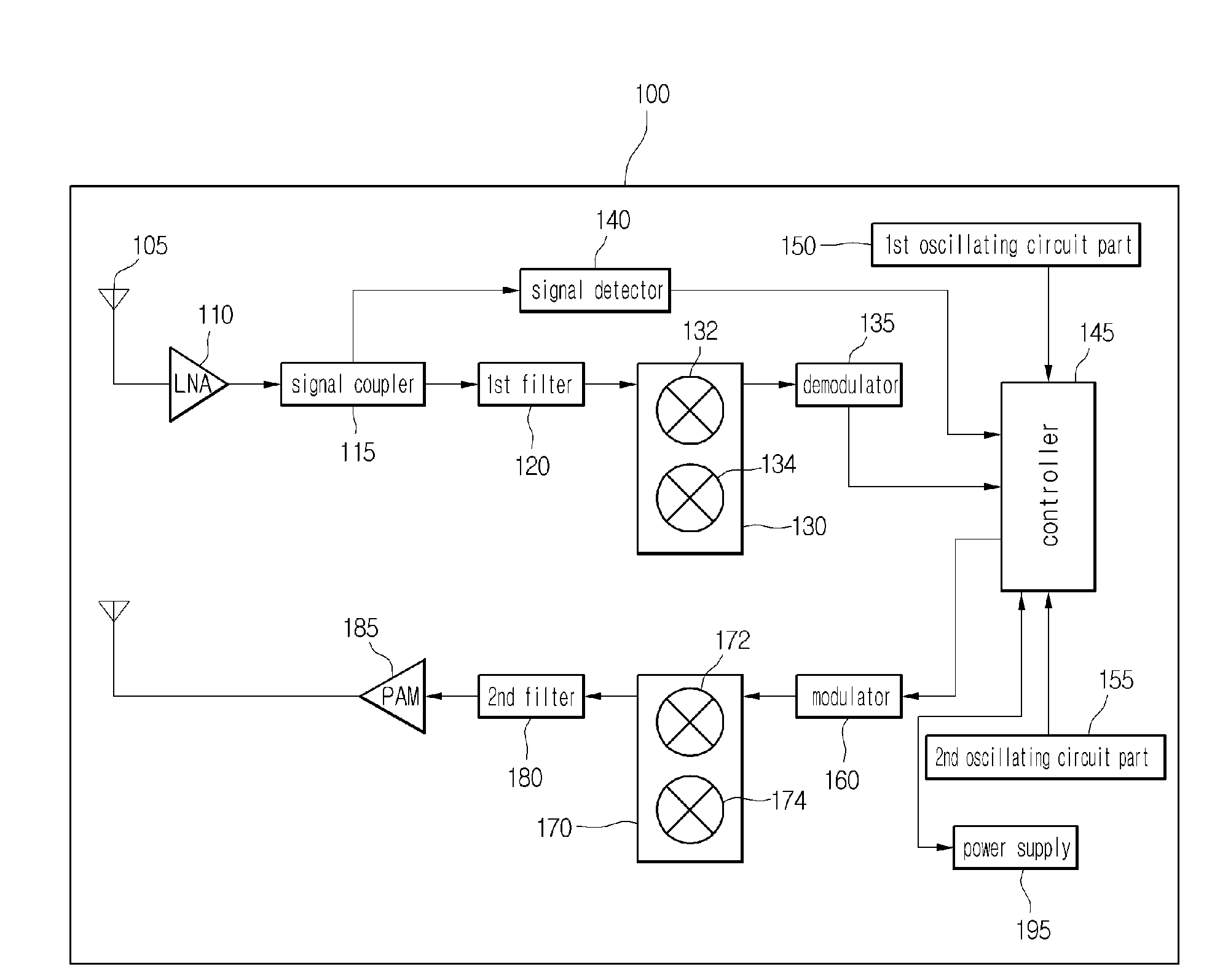
[0021]As shown in FIG. 1, the RF sensor system 100 comprises a first antenna 105, a low noise amplifier (LNA) 110, a signal coupler 115, a first filter 120, a first signal converter 130, a demodulator 135, a signal detector 140, a controller 145, a first oscillating circuit part 150, a second oscillating circuit part 155, a modulator 160, a second signal converter 170, a second filter 180, a power amplifier module 185, a second antenna 190, and a power supply 195.

[0022]The controller 145 controls the power supply 195 such that power is continuously supplied to a receive path terminal including from the low noise amplifier 110 to the demodulator 135. Accordingly, predetermined impedance...


PUM


Abstract

The embodiment provides a radio frequency sensor system comprising a radio frequency transmission terminal and a radio frequency reception terminal. The system comprises an oscillating circuit part for generating a plurality of frequency clocks, a signal coupler for coupling signals exiting on the radio frequency reception terminal, a signal detector for detecting change of the coupled signal according to movement of an object and generating a detection signal, and a controller for analyzing the detection signal and differentially employing the frequency clock according to the analysis result.

Description

TECHNICAL FIELD [0001]The embodiment relates to a radio frequency (RF) sensor system and a method for operating the same.BACKGROUND ART[0002]A ubiquitous network technology has been captured the world's attention. The ubiquitous network technology allows a user to naturally access various networks regardless of time and location.[0003]Such a ubiquitous network technology comprises a radio frequency identification (RFID) technology and a ubiquitous sensor network (USN) technology. Among them, the RFID technology for commercial transaction is representatively employed.[0004]The ubiquitous sensor network (USN) technology is referred to as a network technology of constructing a network such that plural pieces of information collected by various sensors are obtained in wireless. According to the USN technology, a plurality of sensor network nodes are installed in a region where the access of a person is difficult, thereby allowing the person to monitor the region.[0005]An RFID system for...

Claims


Application Information

Patent Timeline
Patent Type & Authority Applications(United States)
IPC IPC(8): H04B1/40
CPCG01D21/00G06K7/0008H04B5/0043G06K7/10207H04B1/40G06K7/10128G06K17/00H04B5/00
Inventor KIM, NAM YUN
Owner LG INNOTEK CO LTD
Why Eureka
Try Eureka