Ultrasound observation device and method for controlling operation thereof

Inactive Publication Date: 2009-12-31
FUJIFILM CORP
View PDF0 Cites 4 Cited by
  • Summary
  • Abstract
  • Description
  • Claims
  • Application Information

AI Technical Summary

Benefits of technology

[0024]Since the display switching process is started immediately after the generation of the switching pulse, the time taken to switch the display of the ultrasound image can be much reduced.
[0025]The second detector detects whether or not the operation member is be

Problems solved by technology

Once the display switching process is started, the single processing circuit cannot accept the subsequent switching pulse until the completion of the running process.
However, the waiting time after each switching pulse prolongs the time taken to switch the display of the ultrasound image, and annoys the operator.
In addition, since every operator makes the switching operation at different speed, the fixed waiting time may be in

Method used


Image

  • Ultrasound observation device and method for controlling operation thereof
  • Ultrasound observation device and method for controlling operation thereof
  • Ultrasound observation device and method for controlling operation thereof

Examples


first embodiment

[0065]Although the waiting time is calculated for each switching operation in the above embodiment, it may be calculated for a series of switching operations. In this instance, as shown in FIG. 6, an operation history database 29 is used to store a plurality of past generation intervals as an operation history. In FIG. 6, the elements similar to those in the first embodiment are designated by the same reference numerals, and the detailed explanations thereof are omitted.

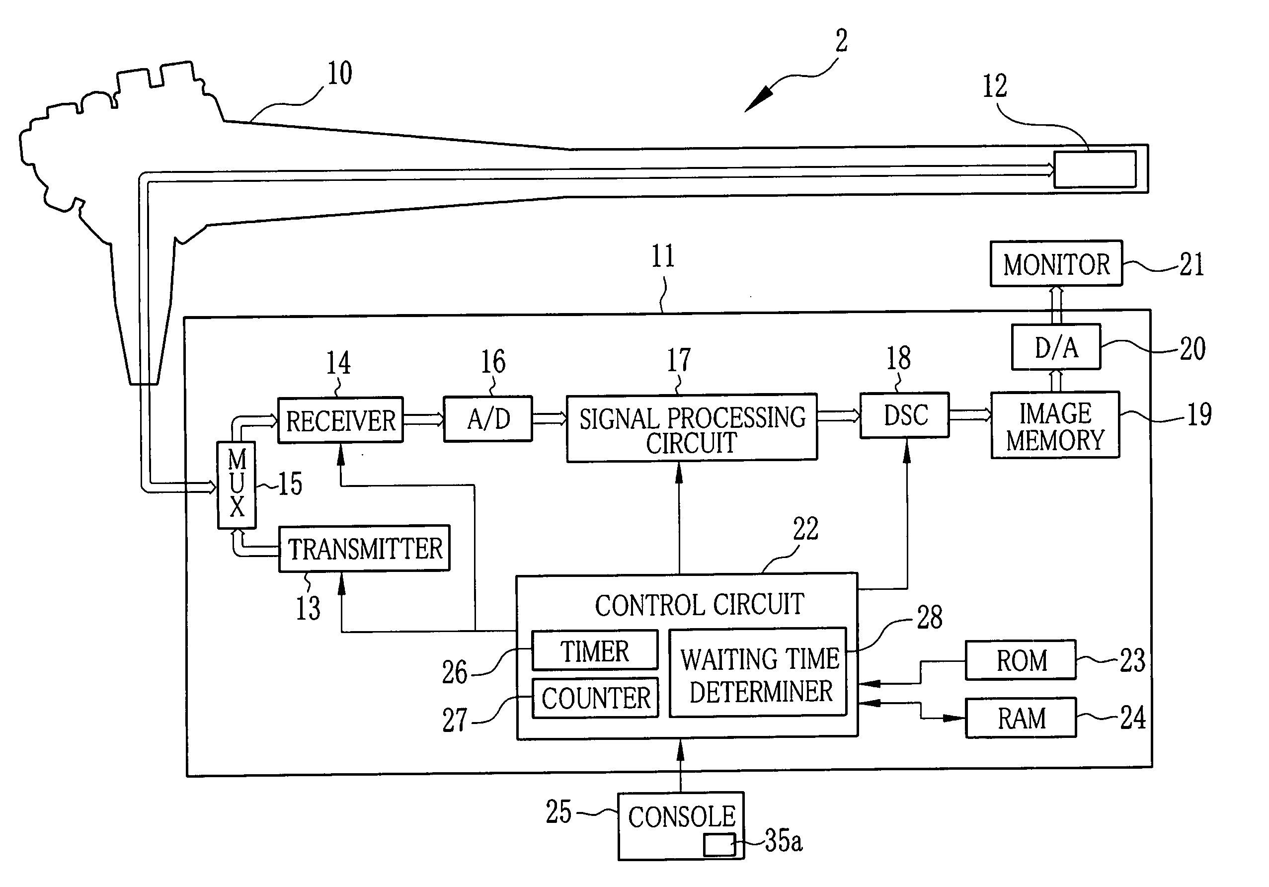
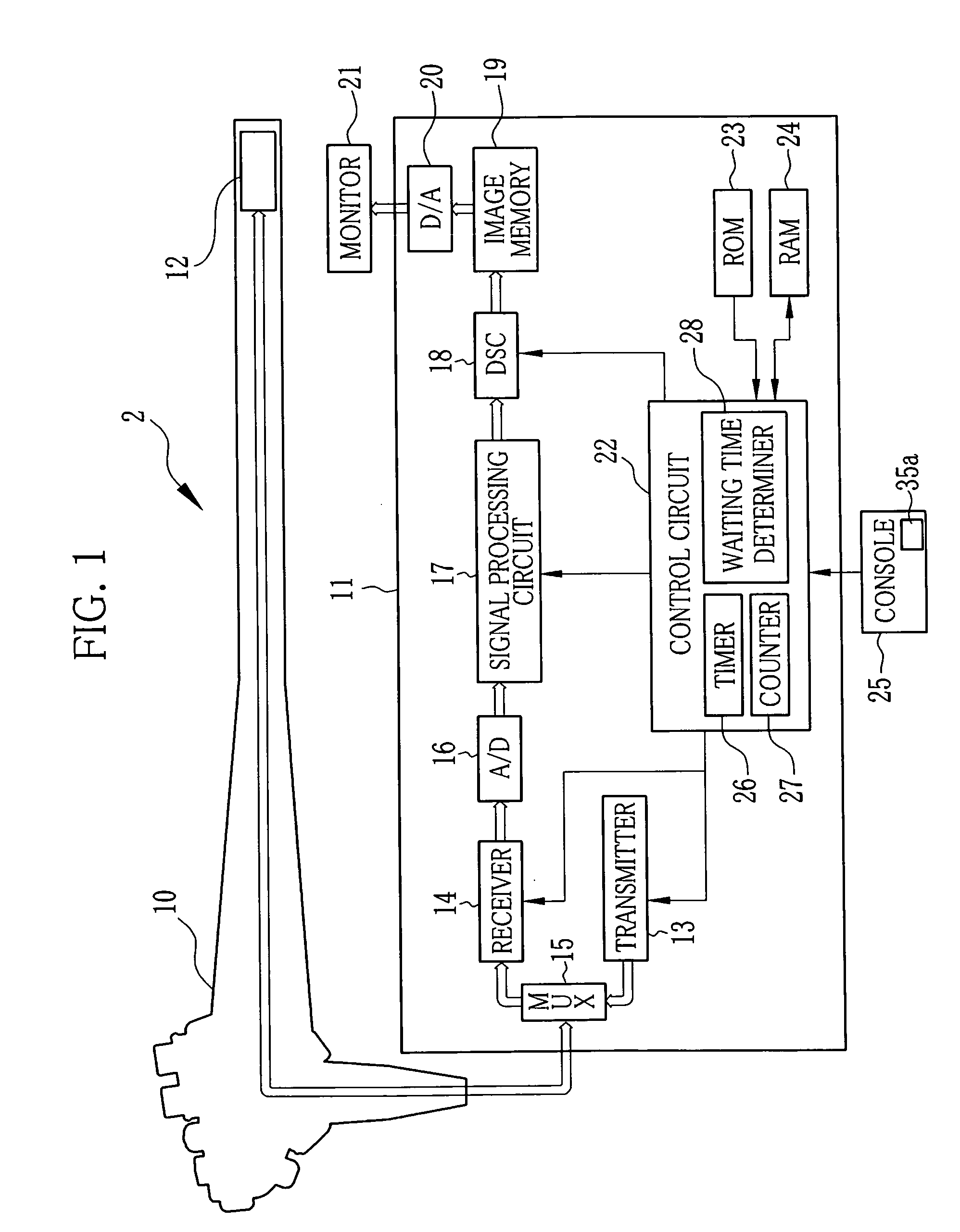
[0066]In FIG. 6, the control circuit 22 includes the timer 26, the waiting time determiner 28 and an operation history database 29. The operation history database 29 stores the previous n-generation intervals, measured on the timer 26, as operation history data. Every time the switching operation is performed to create new data, the oldest operation history data is deleted. The number of the operation history data, or the generation intervals, being stored is predetermined appropriately in accordance with the capacit...

second embodiment

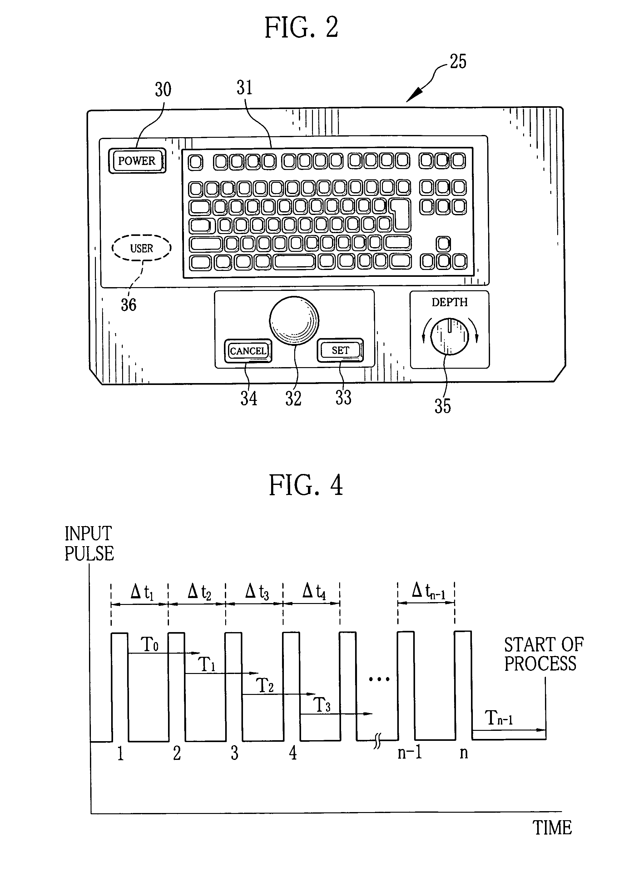
[0072]Next, with reference to a flow chart of FIG. 8, the operation of this second embodiment device is explained. When a first switching pulse is generated from the pulse generator 35a upon rotation of the depth knob 35 (S1), the waiting time determiner 28 retrieves the operation history data from the operation history database 29, and determines the waiting time T (S2). The control circuit 22 starts the timer 26. When the waiting time T elapsed without the generation of a second switching pulse (YES in S3), the display switching process is started under the conditions corresponding to one switching pulse (S8). On the other hand, when the second switching pulse is generated within the waiting time T (YES in S4), a count of the timer 26 at that point is temporarily stored as a generation interval Δt′1 in the RAM 24 (S5). The control circuit 22 resets and starts the timer 26.

[0073]After the generation of the second switching pulse, when the waiting time T elapsed without a third swit...


PUM


Abstract

An ultrasound observation device includes a depth knob and a pulse generator. The depth knob is operated to switch the display depth of an ultrasound image on a monitor. Upon every rotation of the depth knob by a predetermined angle, the pulse generator generates a switching pulse. A control circuit has a waiting time determiner, which determines a waiting time to start signal processing every time the switching pulse is generated. When a subsequent switching pulse is generated within the waiting time, the waiting time determiner calculates an average generation interval of the switching pulses, and determines a new waiting time based on the average generation interval. When the waiting time elapsed without the generation of a subsequent switching pulse, the control circuit recognizes the end of switching operation, and starts a display switching process under the conditions corresponding to the number of the switching pulses generated.

Description

FIELD OF THE INVENTION[0001]The present invention relates to an ultrasound observation device to display an ultrasound image, and a method for controlling operation of the ultrasound observation device.BACKGROUND OF THE INVENTION[0002]In the field of medicine, ultrasound diagnostic apparatus is used for diagnosis of those regions unsuitable for X-ray examination. A typical ultrasound diagnostic apparatus includes an ultrasound probe for transmitting ultrasound waves to a region in a patient's body cavity and receiving reflected ultrasound waves, or echoes, from that region, and an ultrasound observation device connected to the ultrasound probe. The ultrasound observation device applies various types of signal processing to the echo signal received by the ultrasound probe, and generates image data. Based on this image data, an ultrasound image is displayed on a monitor.[0003]Generally, the ultrasound observation devices have a function of switching over ultrasound images displayed on...

Claims


Application Information

Patent Timeline
IPC IPC(8): A61B8/14
CPCA61B8/12A61B8/467G06F3/038G01S7/52084G01S7/52073A61B8/461A61B8/465
Inventor NARUSE, MUTSUMI
Owner FUJIFILM CORP
Why Eureka
Try Eureka