Cryopump

a cryopump and vacuum chamber technology, applied in the field of cryopump, can solve the problems of re-vaporization, cryopump cannot perform further evacuation, and cannot perform further evacuation

Active Publication Date: 2010-01-07
SUMITOMO HEAVY IND LTD
View PDF1 Cites 22 Cited by
  • Summary
  • Abstract
  • Description
  • Claims
  • Application Information

AI Technical Summary

Benefits of technology

[0008]Therefore, a purpose of the present invention is to increase the maximum amount of condensed gas in a cryopump which allows a gas inflow through a side of a radiation shield.
[0010]This may increase the amount of captured gas on the lower structure and mitigate overconcentration on the upper structure. The potential capacity of the lower structure may be effectively utilized and the maximum amount of captured gas may be improved.

Problems solved by technology

When it grows up and contacts to the heat shield plate having a higher temperature, re-vaporization starts and the cryopump does not perform further evacuation.
When the vapor pressure on the surface of the ice layer exceeds the degree of vacuum to be attained, vaporization from the ice layer is predominant over gas condensation from ambient atmosphere to the ice layer, and hence further evacuation cannot be performed.

Method used


Image

  • Cryopump
  • Cryopump
  • Cryopump

Examples


Embodiment Construction

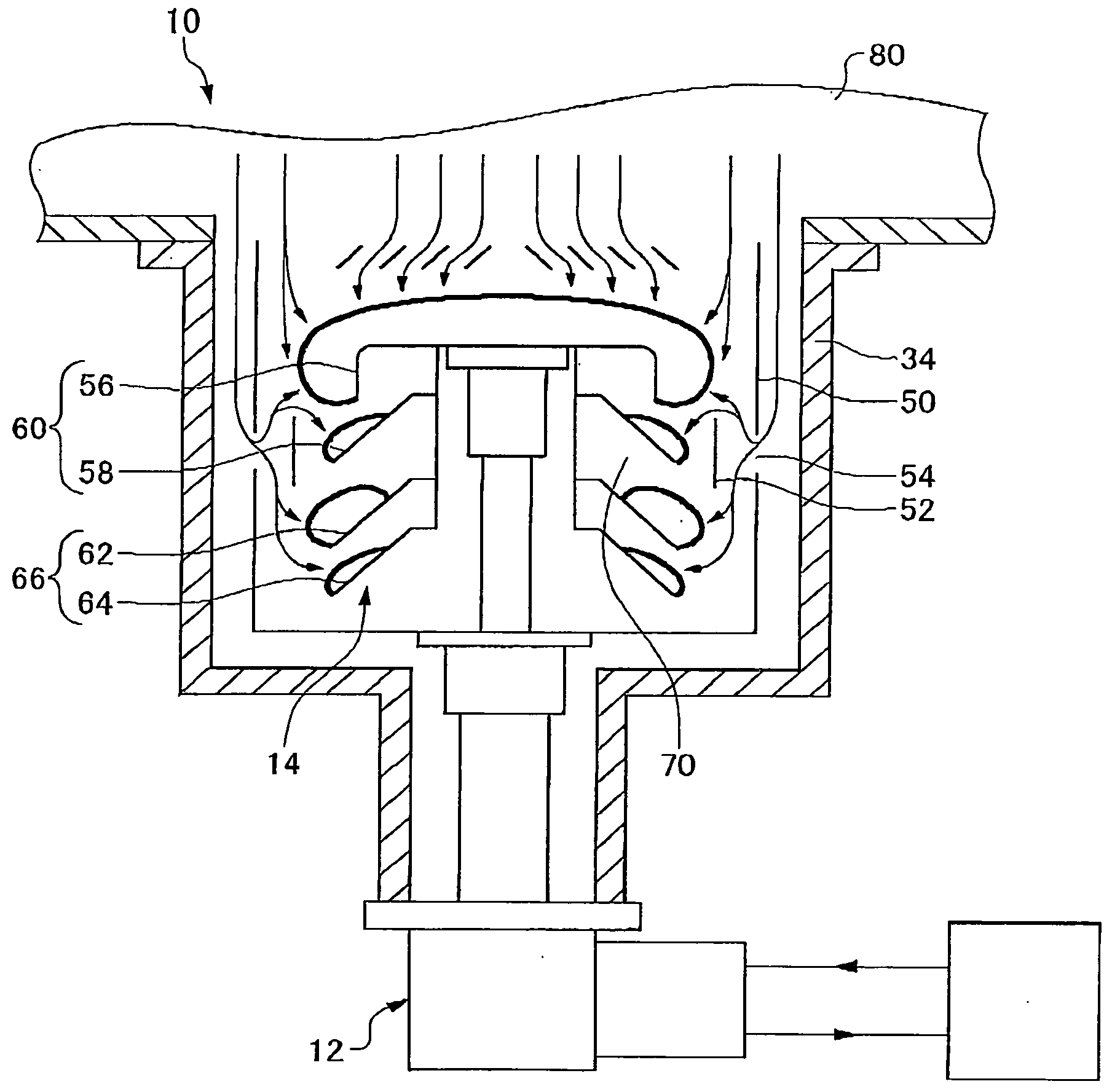
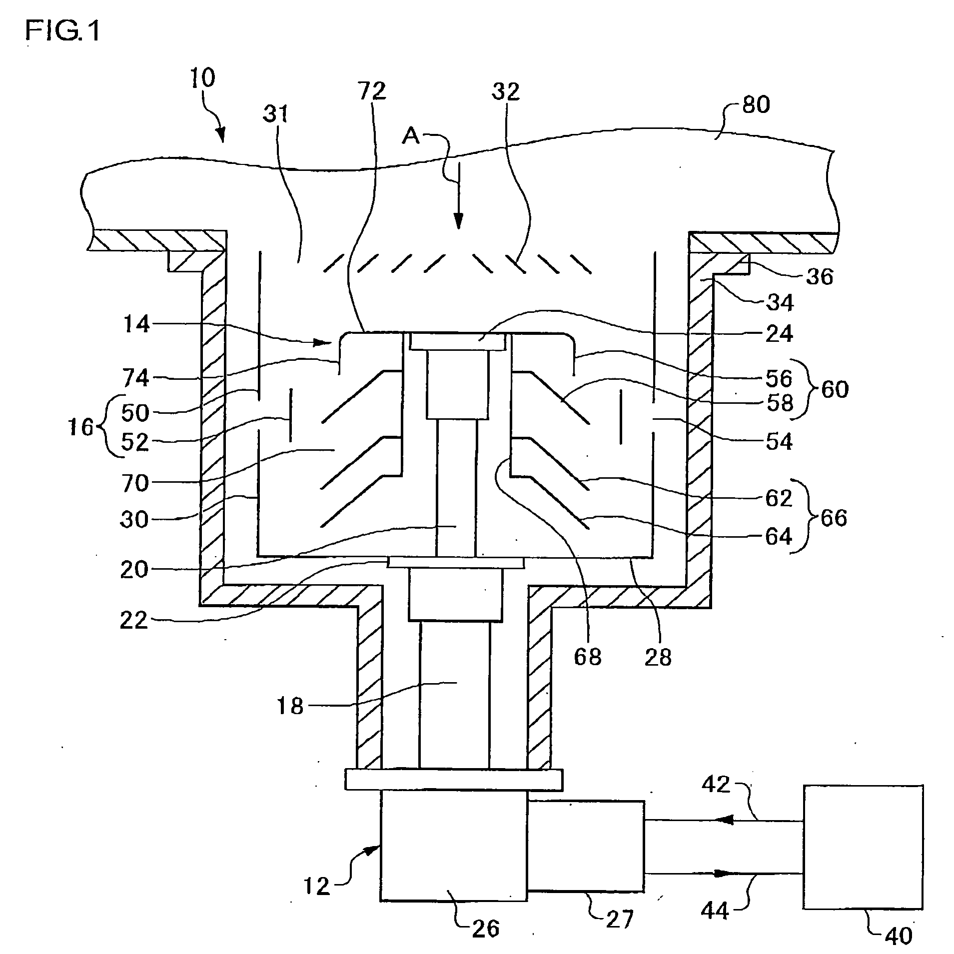
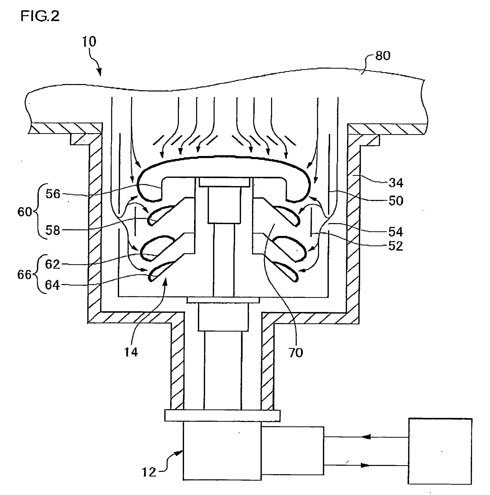
[0017]The present invention will now be described by reference to preferred embodiments. This does not intend to limit the scope of the invention, but to exemplify the invention. According to an embodiment, a cryopump has a cryopanel assembly having a first sub-assembly and a second sub-assembly. The first sub-assembly has at least one cryopanel, and the second sub-assembly also has at least one cryopanel. On a radiation shield surrounding the cryopanel assembly are formed not only a main inlet facing to a cryopump opening but also a sub-inlet. In this cryopump, there is provided a gas inflow path facilitating the incoming of gas molecules to the second sub-assembly. The gas inflow path includes the sub-inlet of the radiation shield, and a frost accommodating space. The accommodating space is formed between the first sub-assembly and the second sub-assembly, i.e., above the second sub-assembly. It facilitates the pumping by the second sub-assembly and mitigates concentration of gas ...


PUM

PropertyMeasurementUnit
vapor pressureaaaaaaaaaa
temperatureaaaaaaaaaa

Abstract

A cryopump includes a radiation shield provided with a main inlet at one end thereof and a sub-inlet in a side thereof; and a cryopanel assembly cooled to a temperature lower than that of the radiation shield. The cryopanel assembly includes an upper structure having at least one cryopanel and a lower structure having at least one cryopanel. The upper and lower structures are arranged inside the radiation shield along a direction away from the main inlet. A frost accommodating space connected to the sub-inlet may be arranged between the upper and lower structures such that an amount of captured gas on an upper end cryopanel of the lower structure is greater than an amount of captured gas on a lower end cryopanel of the upper structure.

Description

BACKGROUND OF THE INVENTION[0001]1. Field of the Invention[0002]The present invention relates to a cryopump.[0003]2. Description of the Related Art[0004]A cryopump is a vacuum pump that captures and pumps gas molecules by condensing or adsorbing molecules on a cryopanel cooled to an extremely low temperature. A cryopanel is generally used to achieve a clean vacuum environment required in a semiconductor circuit manufacturing process.[0005]A cryopump having a heat shield plate provided with a cutout for enabling an inflow of gas molecules and an additional shield for preventing radiation heat from entering through the cutout is disclosed for example in Patent Documents 1 and 2. In this cryopump, a process gas entering into a space between the heat shield plate and the cryopump container is received inside the heat shield plate and is condensed and pumped on the second stage panels. Therefore, the heat transfer from the cryopump container to the heat shield plate via the process gas i...

Claims


Application Information

Patent Timeline
Patent Type & Authority Applications(United States)
IPC IPC(8): F04B37/08
CPCF04B37/08
Inventor TANAKA, HIDEKAZU
Owner SUMITOMO HEAVY IND LTD
Why Eureka
Try Eureka