Refrigeration system

Active Publication Date: 2010-01-07
DAIKIN IND LTD
View PDF1 Cites 2 Cited by
  • Summary
  • Abstract
  • Description
  • Claims
  • Application Information

AI Technical Summary

Benefits of technology

[0027]In the invention, it is arranged such that the liquid refrigerant heading from the heat source side circuit (14) to the utilization side circuit (11) in the cooling operation changes state to a subcooled state. The refrigerant in the subcooled state, even when it undergoes a pressure loss, will not immediately change state to a gas-liquid two-phase state but continues to remain in a liquid state. Therefore, it is possible to provide the supply of refrigerant in a liquid single-phase state to the utilization side circuit (11). As a result, the loss of pressure that the refrigerant undergoes becomes less in comparison with when the refrigerant changes state to a gas-liquid two-phase state by the time that it reaches the utilization side circuit (11). In addition, since the difference in refrigerant enthalpy between the entrance and exit of the utilization side heat exchanger (41) increases and the percentage of liquid refrigerant flowing into the utilization side heat exchanger (41) increases, this enhances the capacity to provide cooling per unit refrigerant flow rate in the utilization side heat exchanger (41). Therefore, it is possible to improve the operation efficiency of the refrigeration system (20).
[0028]In addition, in the second aspect of the invention, the gas refrigerant within the gas-liquid separator (35) is used for the cooling of liquid refrigerant that is fed from the gas-liquid separator (35) to the utilization side circuit (11). The gas-liquid separator (35) will not change state to the state in which gas refrigerant accumulates therein. This therefore facilitates the separation of refrigerant flowing in from the expander (31) into liquid refrigerant and gas refrigerant in the gas-liquid separator (35).
[0029]In addition, in the third aspect of the invention, in the cooling operation, the liquid refrigerant heading from the gas-liquid separator (35) to the utilization side circuit (11) is allowed to exchange heat not only with the refrigerant reduced in temperature by the gas refrigerant pressure reducing mechanism (36) but also with the liquid refrigerant reduced in temperature by the liquid refrigerant pressure reducing mechanism (53). Accordingly, in the cooling heat exchanger (45), the liquid refrigerant heading from the gas-liquid separator (35) to the utilization side circuit (11) is allowed to exchange heat with much more refrigerant, thereby making it possible to increase the degree of subcooling of the liquid refrigerant heading from the gas-liquid separator (35) to the utilization side circuit (11). This therefore ensures that liquid refrigerant is supplied to the utilization side circuit (11) without fail, even when it undergoes a relatively great pressure loss on the way to the utilization side circuit (11).
[0030]In addition, in the fourth aspect of the invention, in the cooling operation, the liquid refrigerant heading from the gas-liquid separator (35) to the utilization side circuit (11) is allowed to exchange heat not only with the refrigerant reduced in temperature by the gas refrigerant pressure reducing mechanism (36) but also with the refrigerant reduced in temperature by the return refrigerant pressure reducing mechanism (55). Accordingly, in the cooling heat exchanger (45), the liquid refrigerant heading from the gas-liquid separator (35) to the utilization side circuit (11) is allowed to exchange heat with much more refrigerant, thereby making it possible to increase the degree of subcooling of the liquid refrigerant heading from the gas-liquid separator (35) to the utilization side circuit (11). This therefore ensures that liquid refrigerant is supplied to the utilization side circuit (11) without fail, even when it undergoes a relatively great pressure loss on the way to the utilization side circuit (11).
[0031]In addition, in the seventh aspect of the invention, the compressor (30) and the expander (31) are connected together by the single drive shaft, whereby the power recovered in association with the expansion of refrigerant in the expander (31) is transmitted to the compressor (30). Accordingly, the power required for driving the compressor (30) can be saved, thereby making it possible to improve the operation efficiency of the refrigeration system (20).
[0032]In addition, in the eighth of the invention, in the cooling operation, the refrigerant, cooled to a subcooled state by the cooling means (36, 45, 53, 55) of the heat source side circuit (14), is fed to each utilization side circuit (11). As described above, the refrigerant in the subcooled state, even when it undergoes a pressure loss, will not immediately change state to a gas-liquid two-phase state but continues to remain in a liquid state. Accordingly, refrigerant in liquid single-phase form can be supplied, as it is, to each utilization side circuit (11).

Problems solved by technology

In other words, it is impossible to provide the supply of refrigerant in a liquid single-phase state to the utilization side circuit.

Method used


Image

  • Refrigeration system
  • Refrigeration system
  • Refrigeration system

Examples


first embodiment

of the Invention

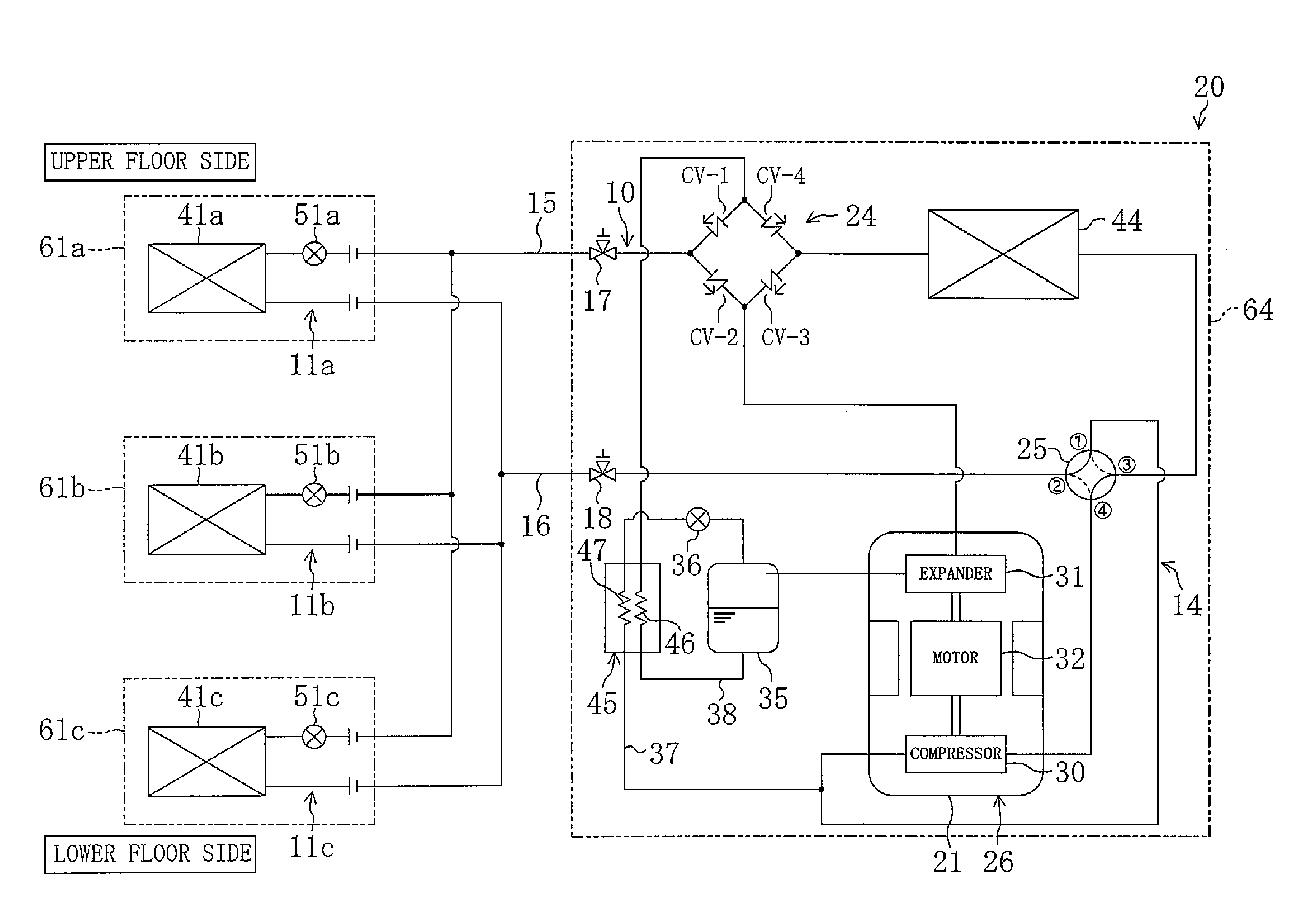
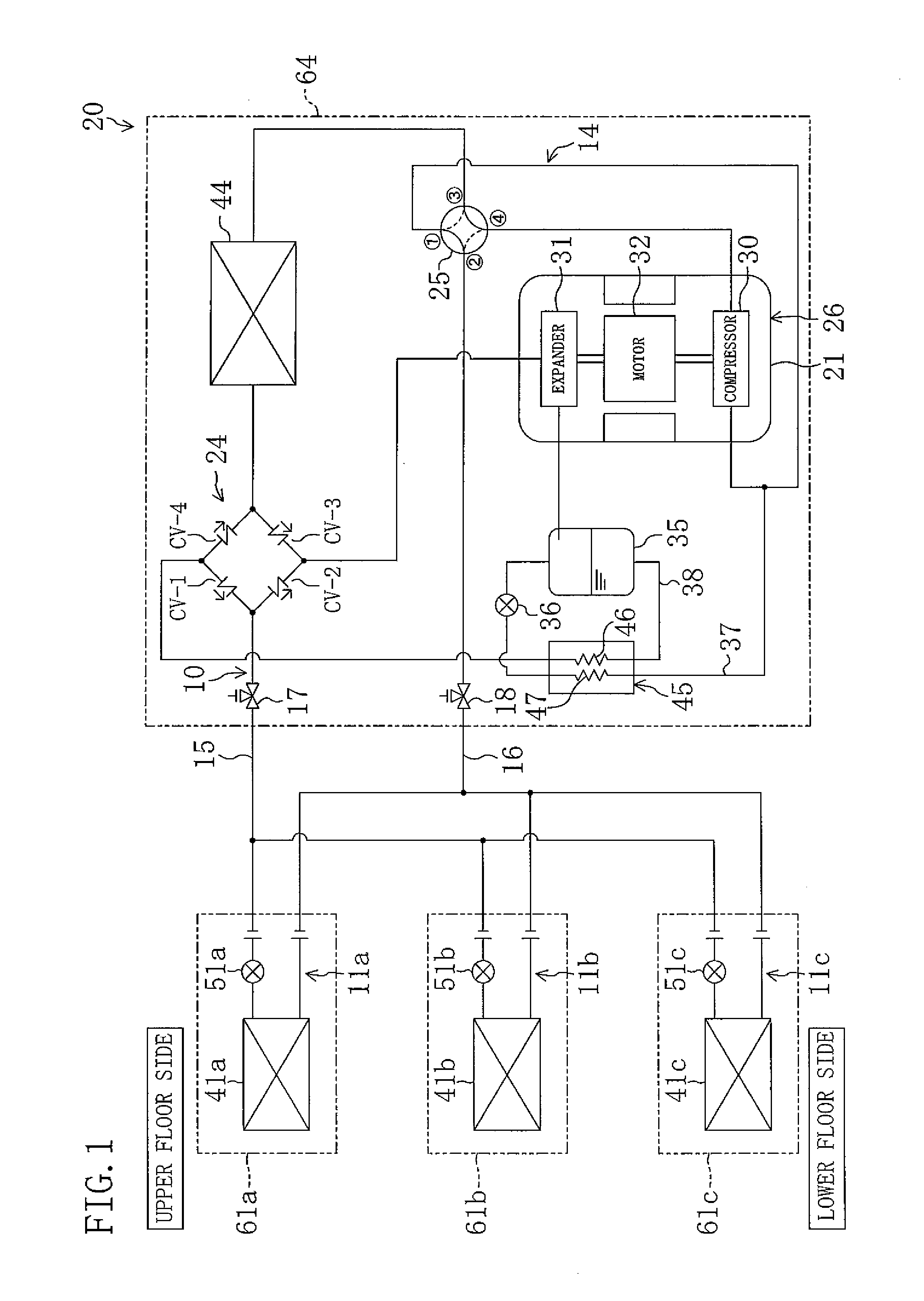
[0068]The following is a description of a first embodiment of the present invention. An air conditioner (20) of the first embodiment is formed by a refrigeration system (20) according to the invention. As shown in FIG. 1, the air conditioner (20) is provided with a single outdoor unit (64) and three indoor units (61a, 61b, 61c). The number of the indoor units (61a, 61b, 61c) shown here is merely exemplary.

[0069]These three indoor units (61a, 61b, 61c) are respectively, a first indoor unit (61a), a second indoor unit (61b) and a third indoor unit (61c). These three indoor units (61a, 61b, 61c) are installed on different floors in a building, wherein the first indoor unit (61a), the second indoor unit (61b) and the third indoor unit (61c) are installed, respectively, on an upper level floor, on an intermediate level floor, and on a lower level floor. The outdoor unit (64) is installed on the lowermost level floor of the building.

[0070]The air conditioner (20) of the fi...

second embodiment

of the Invention

[0114]An air conditioner (20) of a second embodiment of the invention is formed by a refrigeration system (20) according to the invention, as in the first embodiment. Hereinafter, the difference of the second embodiment from the first embodiment will be described.

[0115]As seen from FIG. 6, the gas-liquid separator (35) is not disposed in the outdoor circuit (14) of the second embodiment. In the outdoor circuit (14), the outflow side of the expander (31) is connected, through cooling piping (49) that passes through the internal heat exchanger (28) serving as a subcooling heat exchanger, to the bridge circuit (24).

[0116]One end of the injection pipe (42) is connected, upstream of the internal heat exchanger (28), to the cooling piping (49). The other end of the injection pipe (42) is connected to the suction side of the compressor (30). The injection pipe (42) is provided with a return refrigerant expansion valve (55) which is a return refrigerant pressure reducing mec...

first modification

[0121]With respect to the foregoing embodiments, it may be arranged that there is mounted between the outdoor heat exchanger (44) and the bridge circuit (24) an outdoor expansion valve (43) whose degree of opening is variable, as shown in FIG. 8. In the air conditioner (20) of the first modification, the outdoor expansion valve (43) is fully opened during the space cooling operation. On the other hand, in the space heating operation, the degree of opening of the outdoor expansion valve (43) is adjusted in order to control the degree of superheat of the refrigerant heading to the compressor (30).


PUM


Abstract

A heat source side circuit (14) includes a gas-liquid separator (35) for the separation of refrigerant flowing therein from an expander (31) into liquid refrigerant and gas refrigerant and a cooling means (36, 45, 53, 55) for the cooling of liquid refrigerant heading from the gas-liquid separator (35) to a utilization side circuit (11). Since the refrigerant exiting the gas-liquid separator (35) is in a saturated liquid form, it always changes state to a subcooled state whenever cooled by the cooling means (36, 45, 53, 55).

Description

TECHNICAL FIELD[0001]This invention relates to a refrigeration system capable of performing a cooling operation in which the refrigerant is circulated in a refrigerant circuit so that a heat source side heat exchanger functions as a condenser while a utilization side heat exchanger functions as an evaporator.BACKGROUND ART[0002]Refrigeration systems capable of carrying out a cooling operation have been known in the art. In such a cooling operation, refrigerant is circuited so that, in a refrigerant circuit including a heat source side heat exchanger and a utilization side heat exchanger which are connected together, the heat source side heat exchanger functions as a condenser while the utilization side heat exchanger functions as an evaporator. This type of refrigeration system is used, for example, as an air conditioner for providing air conditioning of an indoor space by means of an indoor unit in which a utilization side heat exchanger is mounted.[0003]JP-A-2006-71137 (hereinafte...

Claims


Application Information

Patent Timeline
IPC IPC(8): F25B27/00F25B43/00F25B41/00
CPCF25B1/10F25B9/008F25B9/06F25B13/00F25B2309/061Y02B30/741F25B2313/0272F25B2313/02741F25B2400/13F25B2400/23F25B2600/0253F25B2313/0233Y02B30/70F25B1/00F25B11/02
Inventor OKAMOTO, MASAKAZU
Owner DAIKIN IND LTD
Why Eureka
Try Eureka