Arrangement for heating oil in a gearbox

a gearbox and arrangement technology, applied in the direction of machines/engines, engine starters, auxiliaries, etc., can solve the problems of reducing the period of time and increasing the fuel consumption of the viscous consistency of the oil, and achieve the effect of reducing the fuel consumption of the combustion engin

Inactive Publication Date: 2010-01-07
SCANIA CV AB
View PDF7 Cites 18 Cited by
  • Summary
  • Abstract
  • Description
  • Claims
  • Application Information

AI Technical Summary

Benefits of technology

[0004]The object of present invention is to provide an arrangement for reducing the fuel consumption of a combustion engine during cold starts.
[0005]This object is achieved with the arrangement of the kind mentioned in the introduction which is characterised by the features indicated in the characterising part of claim 1. During a cold start of a vehicle, the motor oil is warmed relatively quickly by the heat generated by the combustion processes of the combustion engine. It is therefore possible to use the motor oil to warm the oil in the gearbox. With such warming, the oil in the gearbox can undergo almost as rapid warming as the motor oil. The length of the cold start period during which the oil in the gearbox is at too low a temperature and is too viscous can therefore be considerably reduced. The increased fuel consumption arising from the viscous consistency of the oil may thus occur during a reduced period of time. The amount of extra fuel consumed during a cold start of a vehicle with an arrangement as above will therefore be markedly less than in the conventional case. The heat energy used to warm the oil in the gearbox is derived indirectly from the heat energy generated during the combustion processes in the combustion engine. This heat energy is available in the vehicle as soon as the combustion engine has started, so no energy need be stored or supplied externally for warming the oil in the gearbox. The result is no extra cost for the energy used for warming the oil in the gearbox.
[0007]Warm oil which has cooled and lubricated the combustion engine accumulates in the oil pan. The oil in the oil pan thus relatively quickly acquires a raised temperature after starting of the combustion engine. Using the motor oil in the oil pan to warm the oil in the gearbox is therefore advantageous. The first pipe system comprises with advantage a flow means in the form of a pump. The pump may be adapted to starting substantially immediately after the combustion engine is started or as soon as a specified temperature difference between the motor oil in the oil pan and the oil in the gearbox occurs.
[0009]According to another embodiment of the invention, a second pipe system comprises an inlet aperture so positioned that it receives motor oil from an oil pan in the gearbox. Gearboxes are normally provided with an oil pan at a bottom surface to receive and accumulate oil. It is therefore relatively easy to lead oil in from the oil pan to the second pipe system. The second pipe system comprises with advantage a flow means in the form of a pump. The pump may be adapted to starting substantially immediately after the combustion engine has started or as soon as the motor oil in the oil pan has reached a suitably high temperature than the oil in the gearbox.
[0010]According to another preferred embodiment of the invention, the second pipe system comprises an inlet aperture so positioned that it receives motor oil from an oil duct situated downstream of an existing oil pump in the gearbox. At this location the oil has been pressurised by the oil pump. The existing oil pump in the gearbox can therefore be used to circulate oil through the second pipe system. The second pipe system comprises with advantage a flow means in the form of a valve. The fact that in this case oil at above atmospheric pressure is available at an inlet aperture to the second pipe system makes it possible to use a relatively simple valve settable between an open position and a closed position to control the flow of the oil through the second pipe system.

Problems solved by technology

The increased fuel consumption arising from the viscous consistency of the oil may thus occur during a reduced period of time.

Method used


Image

  • Arrangement for heating oil in a gearbox
  • Arrangement for heating oil in a gearbox

Examples


Embodiment Construction

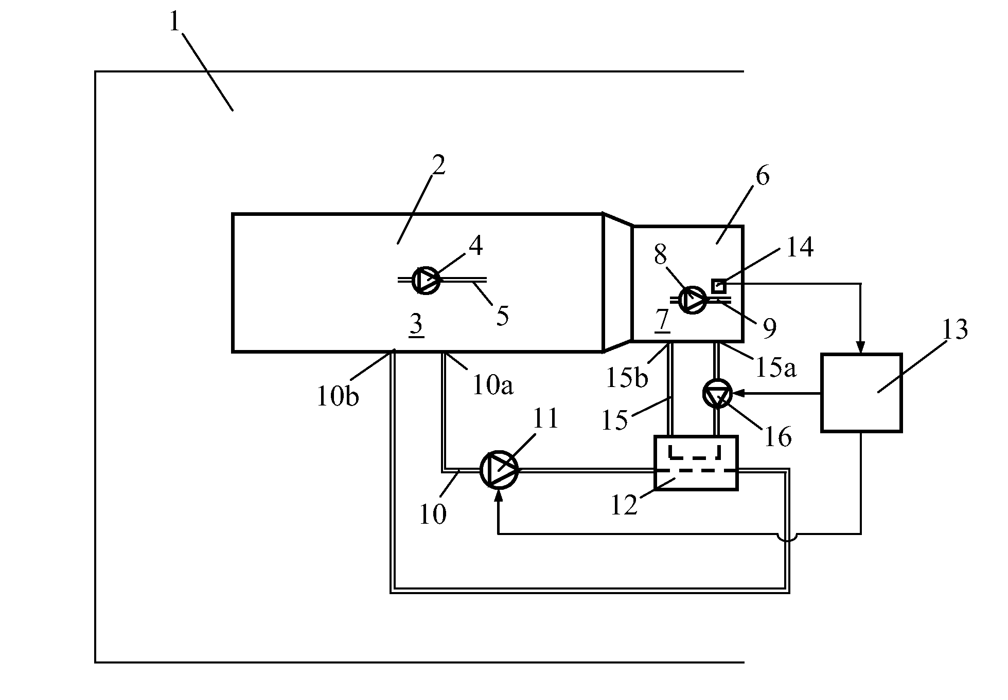
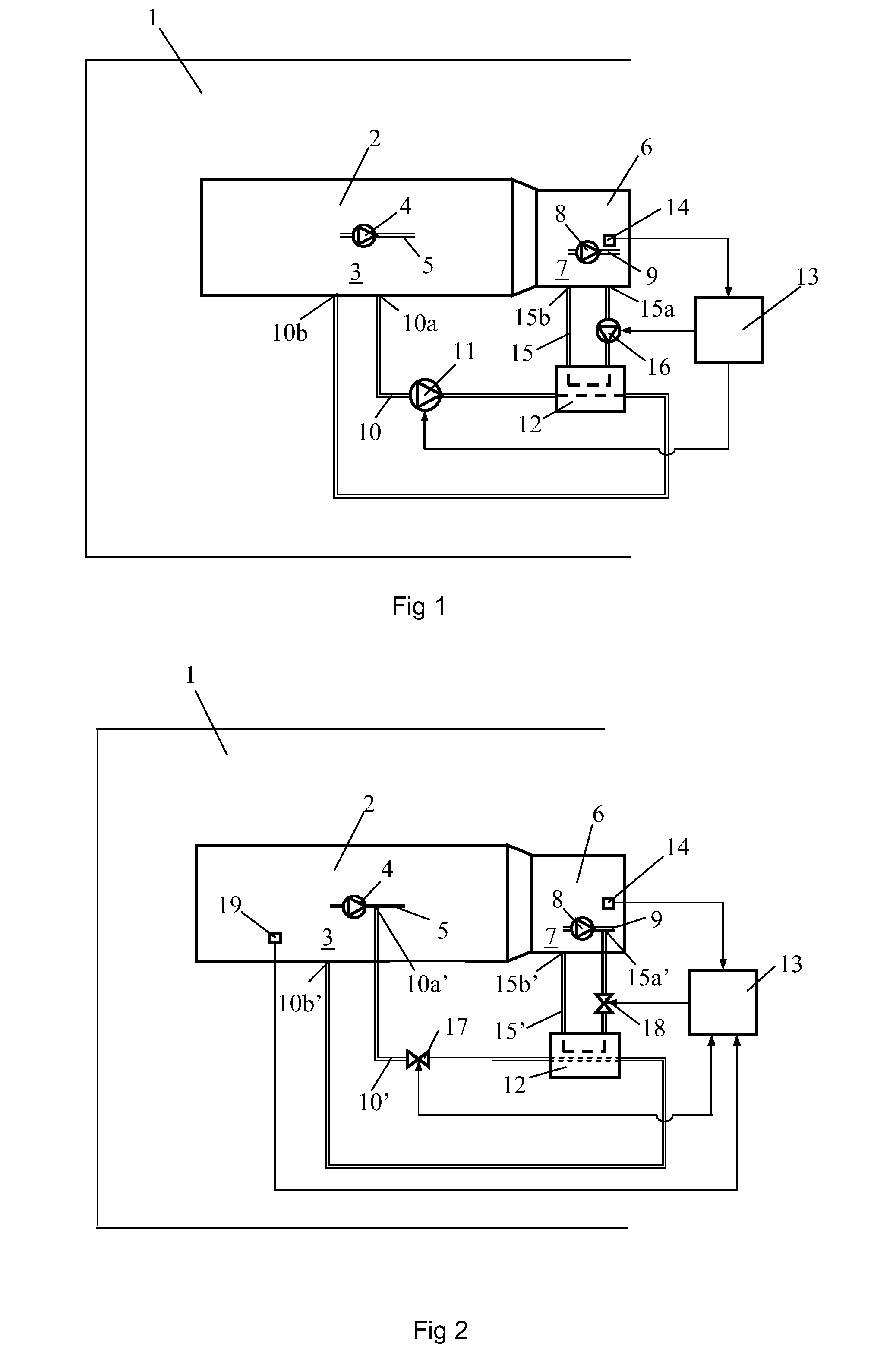
[0015]FIG. 1 depicts schematically a vehicle 1 powered by a combustion engine 2. The vehicle 1 may be a heavy vehicle powered by a combustion engine 2 in the form of a supercharged diesel engine. The combustion engine 2 is in a conventional manner lubricated and cooled by a circulating motor oil. The combustion engine 2 comprises at a bottom surface a schematically depicted oil pan 3 for receiving and accumulating oil. An oil pump 4 is adapted to drawing oil from the oil pan 3. The oil drawn is pushed by the pump 4 through an oil duct 5 to an undepicted oil filter and thereafter through ducts which lead the oil to the points where the engine needs lubrication. When the oil has lubricated said points in the combustion engine, it runs back and accumulates in the oil pan 3. The oil undergoes warming in said ducts by the heat generated during the combustion processes in the combustion engine. The oil in the oil pan 3 thus undergoes relatively rapid warming after starting of the combusti...


PUM


Abstract

An arrangement for warming the oil in a gearbox in a vehicle powered by a combustion engine. A first pipe system with a first flow device which makes possible circulation of oil from the combustion engine through a heat exchanger. A second pipe system with a second flow device makes possible circulation of oil from the gearbox through the heat exchanger. A control device controls the flow devices so that flow of oil through the heat exchanger is obtained in situations in which the oil in the gearbox is at a too low temperature with respect to a desired temperature. The motor oil in the combustion engine can thus be used for heating the oil in the gearbox during cold starts of the combustion engine.

Description

BACKGROUND TO THE INVENTION, AND STATE OF THE ART[0001]Present invention relates to an arrangement for warming of oil in a gearbox according to the preamble of claim 1.[0002]When an engine-powered vehicle is started after a period of being switched off, the oil in a gearbox is at substantially the same temperature as the surroundings. When the surroundings are at a low temperature, the oil in the gearbox is in a more or less viscous state. During cold starts of the vehicle, the viscous consistency of the oil therefore results in the consumption of a large amount of extra energy for driving the components of the gearbox. The viscous consistency of the oil also means that greater force is required for engaging different gears in the gearbox. The oil in the gearbox is mainly warmed by the friction heat generated by the components of the gearbox performing their mechanical work. Such warming is not particularly effective, so a relatively long time may be required for the oil in the gear...

Claims


Application Information

Patent Timeline
Patent Type & Authority Applications(United States)
IPC IPC(8): F01P1/06F01M5/00F02N19/04F16H57/04
CPCF01M5/00F01M5/005F16H57/0475F02N19/04F16H57/0413F01M5/02F01M5/021F01P11/08F16H57/0405F16N39/04
Inventor KARDOS, ZOLTANWIKSTROM, HANSSODERBERG, ERIK
Owner SCANIA CV AB
Why Eureka
Try Eureka