
Photovoltaic dc/dc micro-converter

a photovoltaic and micro-converter technology, applied in the direction of dc network circuit arrangement, pv power plants, semiconductor devices, etc., can solve the problems of reducing the performance, i.e., dc output, of the entire pv array, and increasing the difficulty of efficiently managing power, etc., to achieve efficient control, maximize design flexibility, and enhance longevity

Active Publication Date: 2010-01-07
PERFECT GALAXY INT
View PDF47 Cites 327 Cited by
  • Summary
  • Abstract
  • Description
  • Claims
  • Application Information

AI Technical Summary

Benefits of technology

[0024]The photovoltaic power system is structured and arranged to maximize design flexibility, which leads to enhanced longevity. For example, different panel technologies, vintages, sizes, mounts, and manufacturing brands can be incorporated into the same array, which can be efficiently controlled by the disclosed invention. The range of power ratings for the disclosed system is between 30 kW and 1 MW.
[0025]Managerial benefits include increased visibility which includes in-depth diagnostic and performance information, enabling the conditions of PV strings and / or corresponding DC / DC converters to be monitored remotely. As a consequence, poorly performing or malfunctioning PV strings or PV strings having ground faults can be systematically isolated without interrupting throughput from the remaining PV strings.
[0026]From a performance standpoint, both energy throughput and return on investment (ROI) can be increased significantly. Indeed, eliminating losses that otherwise would occur when outputs from PV string in parallel are combined and processed reduces the cost per kWh through the lifespan of the PV array. An increase in output of between 5 and 20 percent is predicted.

Problems solved by technology

As photovoltaic (PV) solar power installations continue to increase in number and in scale, harvesting and managing power efficiently has become more challenging.
Equally as challenging is the management of PV power installations on a national level via a “smart grid”.
However, the deleterious effects of shading, soiling, and other lighting degradation on individual PV modules and, hence, PV module characteristics matching require greater consideration.
Matching creates considerable labor and expense during manufacture at the factory.
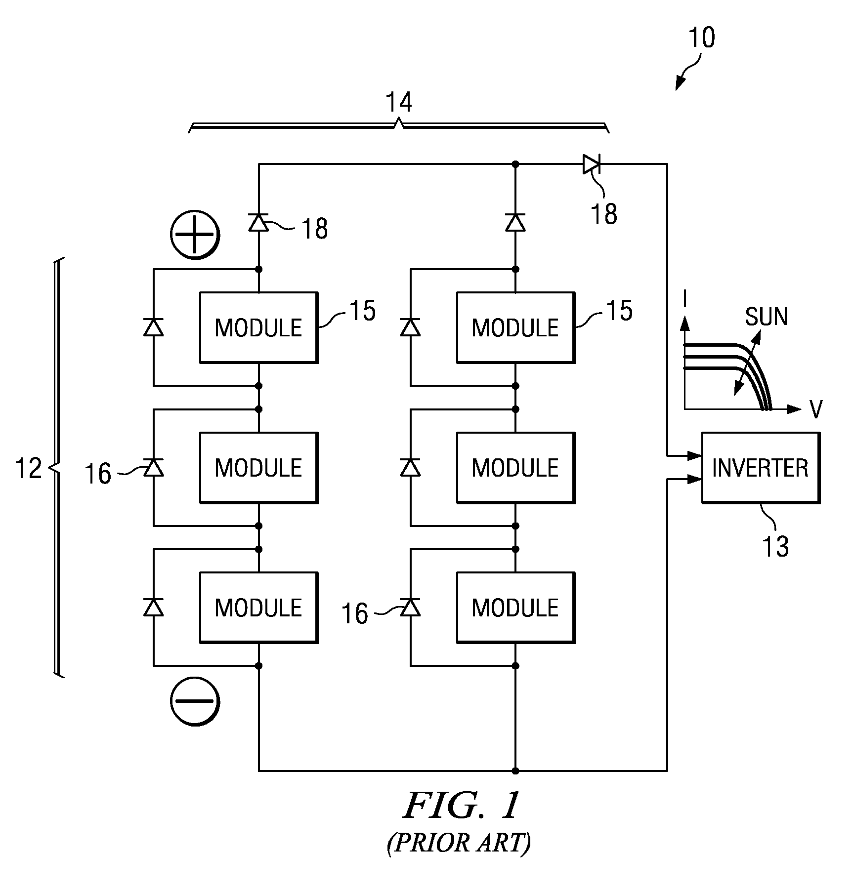
More problematically, even if PV modules 15 are ideally matched at the time of manufacture, a single PV module 15 in any string 12 can quickly degrade the performance, i.e., DC output, of the entire PV array 10.
Moreover, the affected PV module(s) 15 may suffer from excessive heating.
Disadvantageously, there is no PV string level management or control.
Hence, overall array performance is still adversely affected by underperforming individual strings.
Indeed, panel mismatch resulting from, inter alia, shading, soiling, and the like, reduces efficiency.
Disadvantageously, as with centralized inverters, there is no PV string level management or control, which, along with parallel processing and panel mismatch, reduces efficiency.
Furthermore, although the inverters themselves do not include transformer circuitry, a transformer is still required to step up the power delivered to a commercial or utility grid.
Disadvantageously, micro-inverters involve complex electronics that may require sophisticated cooling.
Moreover, large-scale applications may require servicing and maintaining hundreds—if not thousands—of units, which have not yet been engineered to operate dependably for 20 years or more.
Moreover, although generating single phase AC power, the micro-inverter has double line frequency energy storage requirements.
This generally causes either a significant ripple current through the PV module 15—which reduces yield—or requires utilization of electrolytic capacitors.
Electrolytic capacitors, however, are unreliable and the acknowledged “Achilles heel” of any power conversion system that utilizes them.
Furthermore, integrating energy storage into a PV array 10 with micro-inverters is not straightforward.

Method used


Image

  • Photovoltaic dc/dc micro-converter
  • Photovoltaic dc/dc micro-converter
  • Photovoltaic dc/dc micro-converter

Examples


Embodiment Construction

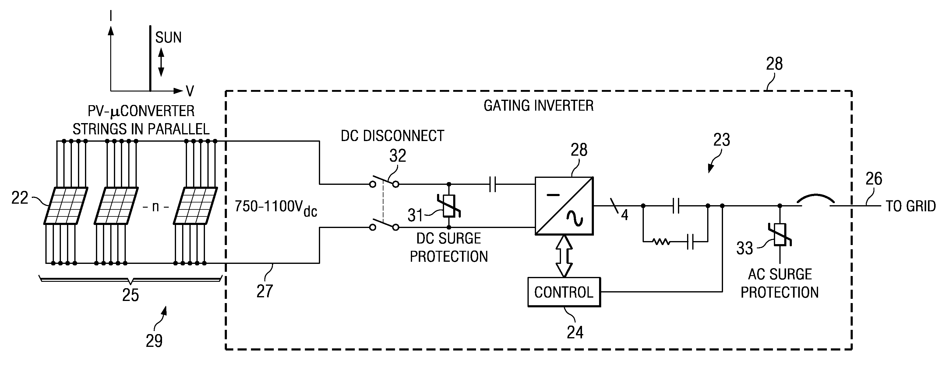
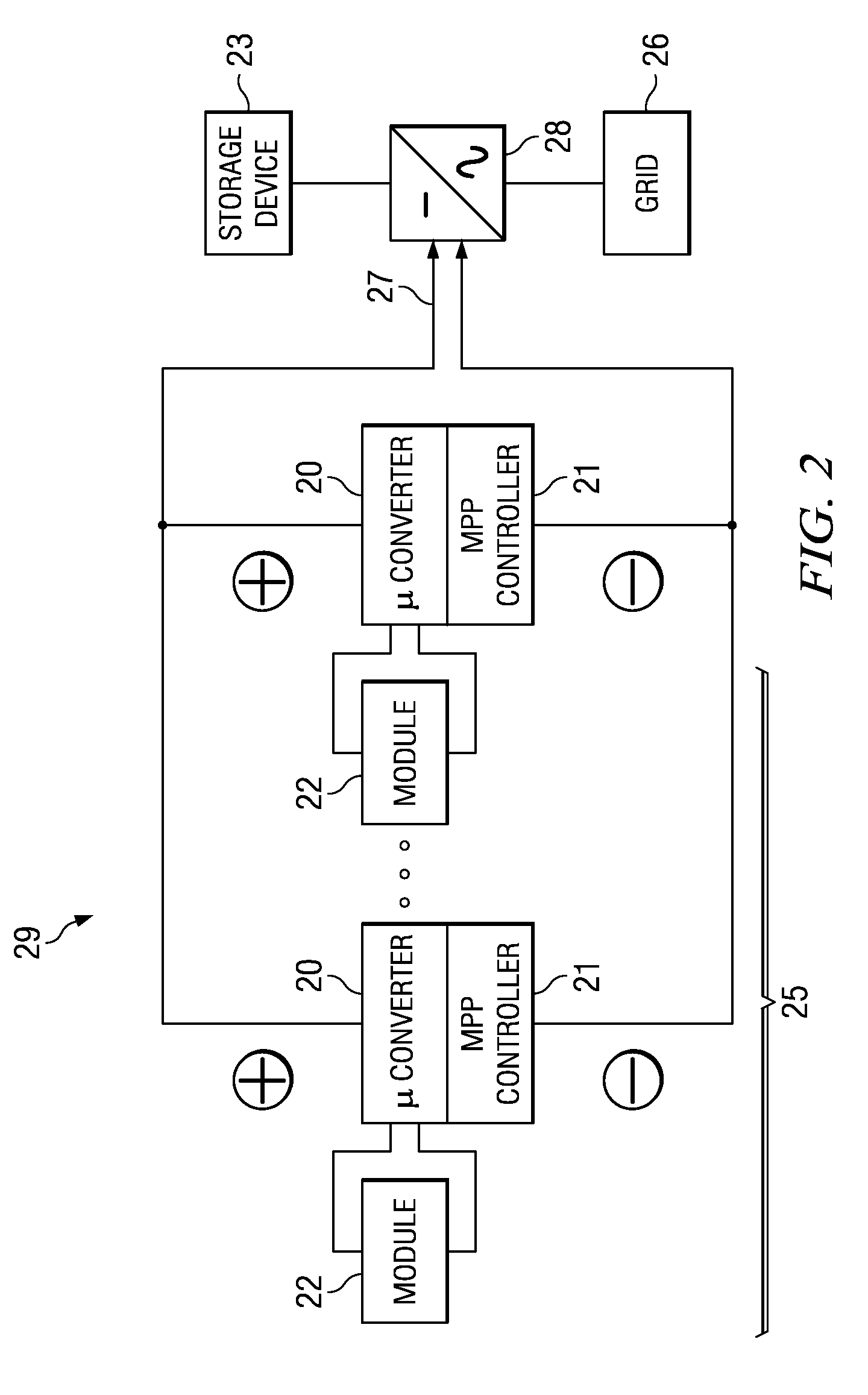
[0033]Referring to FIGS. 2-5 a photovoltaic (PV) system controlled at the string-level by plural DC / DC micro-converters will now be described. The PV system 29 and, more specifically, the control system 21 for the PV system 29 is structured and arranged to extract maximum individual string power (hereinafter, the “Maximum Power Point” or “MPP”) from each of the PV modules 22 in each string of serial-connected PV modules 25 that make up the power-generating portion of the PV system 29.

[0034]The desirability of string-level control is shown illustratively in FIG. 5, which shows current-voltage curves 52, 54, and 56 for three discrete strings of PV modules. Each of the curves 52, 54, and 56 includes an MPP 55 at some location on the curves. The MPP 55 refers to the point of maximum power for an entire string 25 of PV modules 22.

[0035]Because of expected mismatch between PV strings 25, the corresponding MPPs 55 for each string 25 occur or may occur at different currents and / or at differ...


PUM


Abstract

A photo-voltaic (PV) power generating system and a control system for PV array string-level control and PV modules serially-connected into strings of PV modules. The system includes plural parallel strings of serially-connected power-generating photovoltaic modules that form a PV array, DC / DC micro-converters that are coupled to a DC voltage buss and to the output of a corresponding photovoltaic module or to the output of a string of photovoltaic modules; a gating or central inverter; and a control system. The control system is structured and arranged to control and manage each string of photovoltaic modules, to ensure that power delivered by the photovoltaic power generating system is not affected by photovoltaic modules or strings of photovoltaic modules that are not operating at maximum power transfer efficiency.

Description

CROSS REFERENCE TO RELATED APPLICATIONS[0001]Priority of U.S. Provisional Patent Application 61 / 133,634 filed on Jul. 1, 2008 is claimed.STATEMENT REGARDING FEDERALLY SPONSORED RESEARCH OR DEVELOPMENT[0002]Not applicableBACKGROUND OF THE INVENTION[0003]A power converter for use with photovoltaic cells is disclosed, or, more particularly, individual DC / DC micro-converters for dedicated use with at least one photovoltaic module is disclosed.[0004]As photovoltaic (PV) solar power installations continue to increase in number and in scale, harvesting and managing power efficiently has become more challenging. Equally as challenging is the management of PV power installations on a national level via a “smart grid”. In particular, it is desirable to increase the demand for renewable energy, to supplement and / or replace energy produced via fossil fuels. Enhancing PV power use, however, requires reduction in the production cost per kilowatt hour and reduction in utility transaction costs for...

Claims


Application Information

Patent Timeline
IPC IPC(8): H02J1/00H01L31/042
CPCH01L31/02021H01L31/042Y02E10/563H02J3/383H02J1/102H02S40/32H02J2300/24H02J3/381Y02E10/56H02J2300/26H02J3/46
Inventor CASEY, LEO FRANCISPRESTERO, MARK GEORGERAJDA, JANOS
Owner PERFECT GALAXY INT
Learn More