System, apparatus and method for interleaving data bits or symbols

a data bit and symbol technology, applied in the field of data communication, can solve the problems of increasing the errors of received decoded bits, relatively expensive equalization schemes, and transmission symbols susceptible to noise and other channel disruptions

Inactive Publication Date: 2010-01-07
KONINKLIJKE PHILIPS ELECTRONICS NV
View PDF9 Cites 52 Cited by
  • Summary
  • Abstract
  • Description
  • Claims
  • Application Information

AI Technical Summary

Problems solved by technology

However, a standard single-carrier system typically requires an equalization scheme that is relatively expensive to implement.
The transmitted symbols are susceptible to noise and other channel disruptions.
Bursty channel conditions tend to result in increased errors in received decoded bits, especially when the transmitted symbols are in close proximity in time or space.
However, it is more difficult for an FEC decoder to take advantage of the redundancy inserted in the transmitted data when errors are due to bursts.
Bursty disruptions are more likely to corrupt bits or symbols in close proximity, including the redundant bits provided in accordance with an error correction code
However, this conventional technique suffers from drawbacks.
This periodic nature of the block interleaver, leaves the data vulnerable to specific error and noise patterns.
For example, when the noise appears in a periodic fashion, it is likely that all of the redundant symbols / bits will face a higher noise or error level.

Method used


Image

  • System, apparatus and method for interleaving data bits or symbols
  • System, apparatus and method for interleaving data bits or symbols
  • System, apparatus and method for interleaving data bits or symbols

Examples


example 1

INTERLEAVING METHOD EXAMPLE 1

Diagonal Write Operation

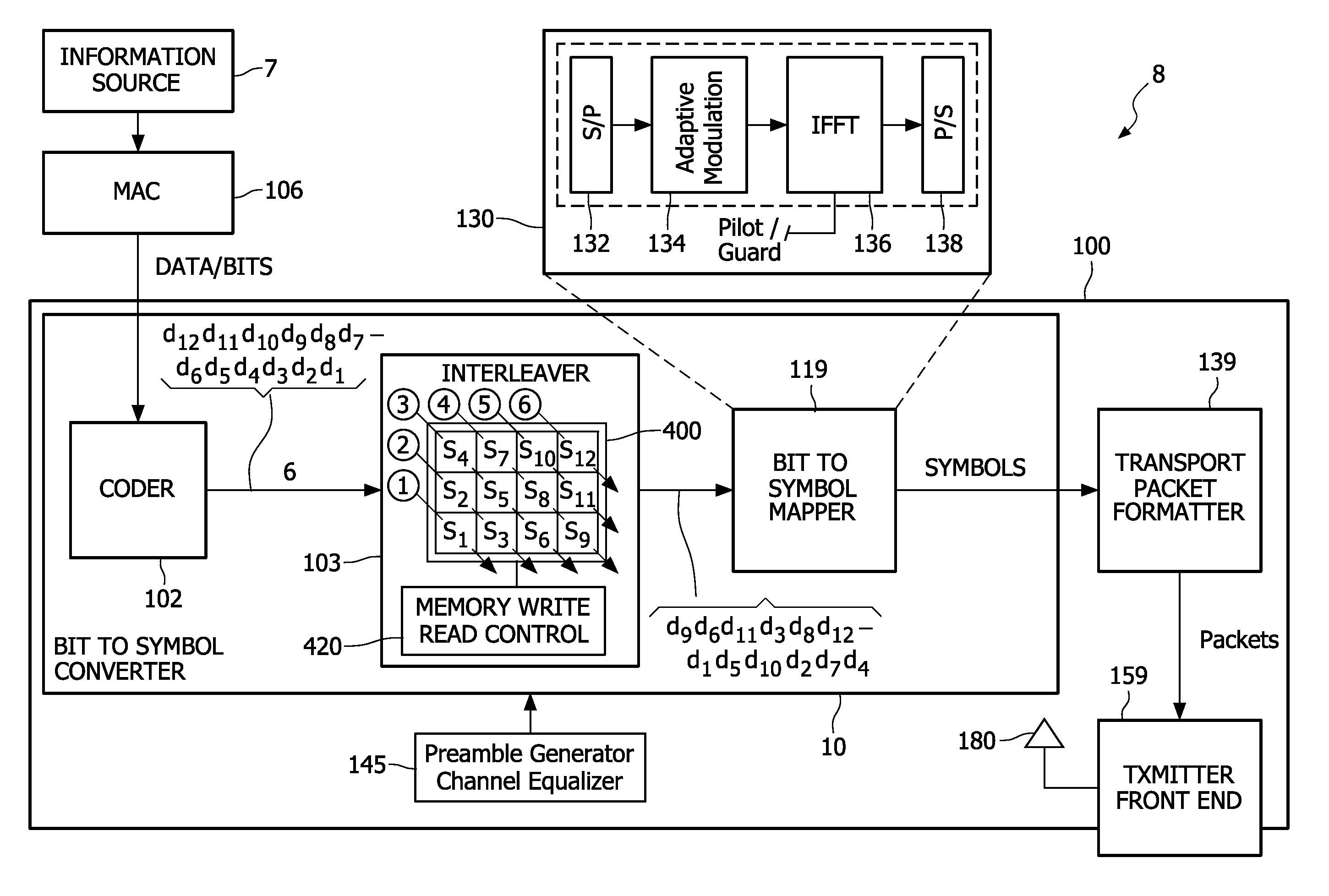
[0083]FIG. 5 is a flow chart illustrating steps of a method for generating a diagonal write sequence according to an embodiment of the invention. For ease of discussion, the method steps are described with reference to the write diagonals (451-456) illustrated in the interleaver apparatus of FIG. 4.

[0084]With reference to the flowchart of FIG. 5, the method begins by writing a first diagonal (451 of FIG. 4) with a first bit S1 of the bit sequence 490. First bit 490 is written to the cell defined by the last row N (in FIG. 4 last row N is row N) and the first column M-1 of memory 400. This cell defines a first diagonal 451 of memory 400.

[0085]The next successive bit S2 of bit sequence 490 is written to a first cell of a second diagonal (452 in FIG. 4). To define a first diagonal write direction (upper left to lower right as indicated at 407 of FIG. 4) for one embodiment of the invention, the second diagonal is defined by a first ce...

— example 3

CONVERTER—EXAMPLE 3

[0097]FIG. 13 is a functional block diagram of a bit to symbol converter 1300 according to an alternative embodiment of the invention. Bit to symbol converter 1300 comprises a serial to parallel converter (S / P), a plurality of encoders 1301-1313, a plurality of mappers 1305-1315, a parallel to serial converter (P / S) 1311 and an interleaver 1320. Bit to symbol converter 1330 receives a first serial bit sequence 1302 at an input of converter 1330. The bit sequence is provided to S / P 1304. S / P 1304 divides the sequence into a plurality of parallel bit sequences. For purposes of discussion three parallel bit sequences are illustrated at an output of S / P 1304 in FIG. 13. However, the invention is not limited as to the number of parallel bit sequences provided by S / P 1304.

[0098]Each bit sequence at an output of S / P 13-4 is provided to a corresponding encoder 1301-1313. Encoders 1301-1313 encode the bit sequences and provide encoded bit sequences at respective outputs. E...

— example 4

CONVERTER—EXAMPLE 4

[0100]FIG. 14 is a functional block diagram of a bit to symbol converter 1400 according to an alternative embodiment of the invention. Bit to symbol converter 1400 comprises a serial to parallel converter (S / P) 1403, a plurality of encoders 1405-1411, a plurality of interleavers 1413-1417 a plurality of mappers 1419-1428, and a parallel to serial converter (P / S) 1429. Bit to symbol converter 1400 receives a first serial bit sequence 1401 at an input of converter 1400. The bit sequence is provided to an input of S / P 1403. S / P 1403 divides the sequence into a plurality of parallel bit sequences. For purposes of discussion three parallel bit sequences are illustrated at an output of S / P 1403 in FIG. 14. However, the invention is not limited as to the number of parallel bit sequences provided by S / P 1403.

[0101]Each bit sequence at an output of S / P 1403 is provided to a corresponding encoder 1405-1411. Encoders 1405-1411 encode the bit sequences and provide encoded bit...


PUM


Abstract

A data transmission system respectively encodes successive bits representing information to be transmitted. An interleaver receives the bits from the encoder and interleaves the bits. The interleaver includes a memory and a memory read write controller configured to write the bits to the memory in accordance with a diagonal write pattern and to read the bits from the memory in a diagonal read pattern. A symbol mapper receives the interleaved bits and maps the encoded interleaved bits into symbols using a transmission format.

Description

CROSS REFERENCE TO RELATED APPLICATIONS[0001]This application claims the benefit of prior filed, co-pending U.S. provisional application: Ser. No. 60 / 885,143, filed on Jan. 16, 2007.BACKGROUND OF THE INVENTION[0002]1. Field of the Invention[0003]This invention pertains to the field of data communications, and more particularly to a system and method of interleaving bits or symbols, suitable for deployment in a variety of transmission systems including, but not limited to, Orthogonal Frequency Division Modulation (OFDM) systems and Single Carrier Block Transmission (SCBT) systems.[0004]2. Description of the Related Art[0005]Data communication systems may be classified in a number of ways according to the transmission schemes they employ. One classification distinguishes between multi carrier communication systems and single carrier communication systems. OFDM is an example of a multi carrier communication scheme. SCBT is an example of a single carrier communication scheme.[0006]The c...

Claims


Application Information

Patent Timeline
Patent Type & Authority Applications(United States)
IPC IPC(8): H04K1/10G06F12/00H03M13/17G06F11/10H03M13/23
CPCH04L5/0007H03M13/2721H04L1/0071H03M13/00H03M13/27H04L5/02
Inventor SEYEDI-ESFAHANI, SEYED-ALIREZA
Owner KONINKLIJKE PHILIPS ELECTRONICS NV
Why Eureka
Try Eureka