Helical implant having different ends

Active Publication Date: 2010-01-07
CR BARD INC
View PDF99 Cites 60 Cited by
  • Summary
  • Abstract
  • Description
  • Claims
  • Application Information

AI Technical Summary

Benefits of technology

[0009]One aspect includes an implantable stent. The implantable stent includes an intermediate portion, first end portion, second end portion, and a coupling portion. The intermediate portion has a first continuous helical winding defining a plurality of circumferential sections circumscribing a longitudinal axis from a first end to a second end to define a portion of essentially a tube. The circumferential sections are spaced apart along the longitudinal axis. Each circumferential section has undulations disposed about a portion of the tube. The fir

Problems solved by technology

Other manufacturing techniques have been proposed, such as vacuum or chemical deposition of material or

Method used


Image

  • Helical implant having different ends
  • Helical implant having different ends
  • Helical implant having different ends

Examples


Example

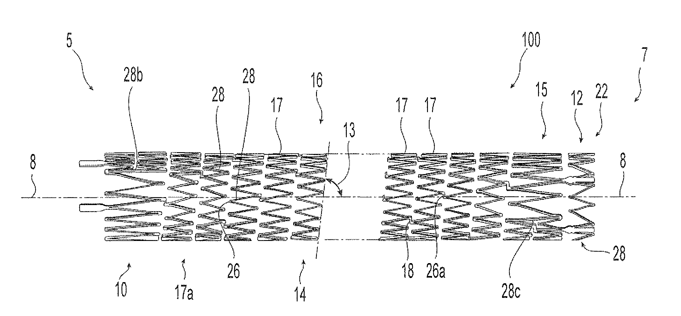
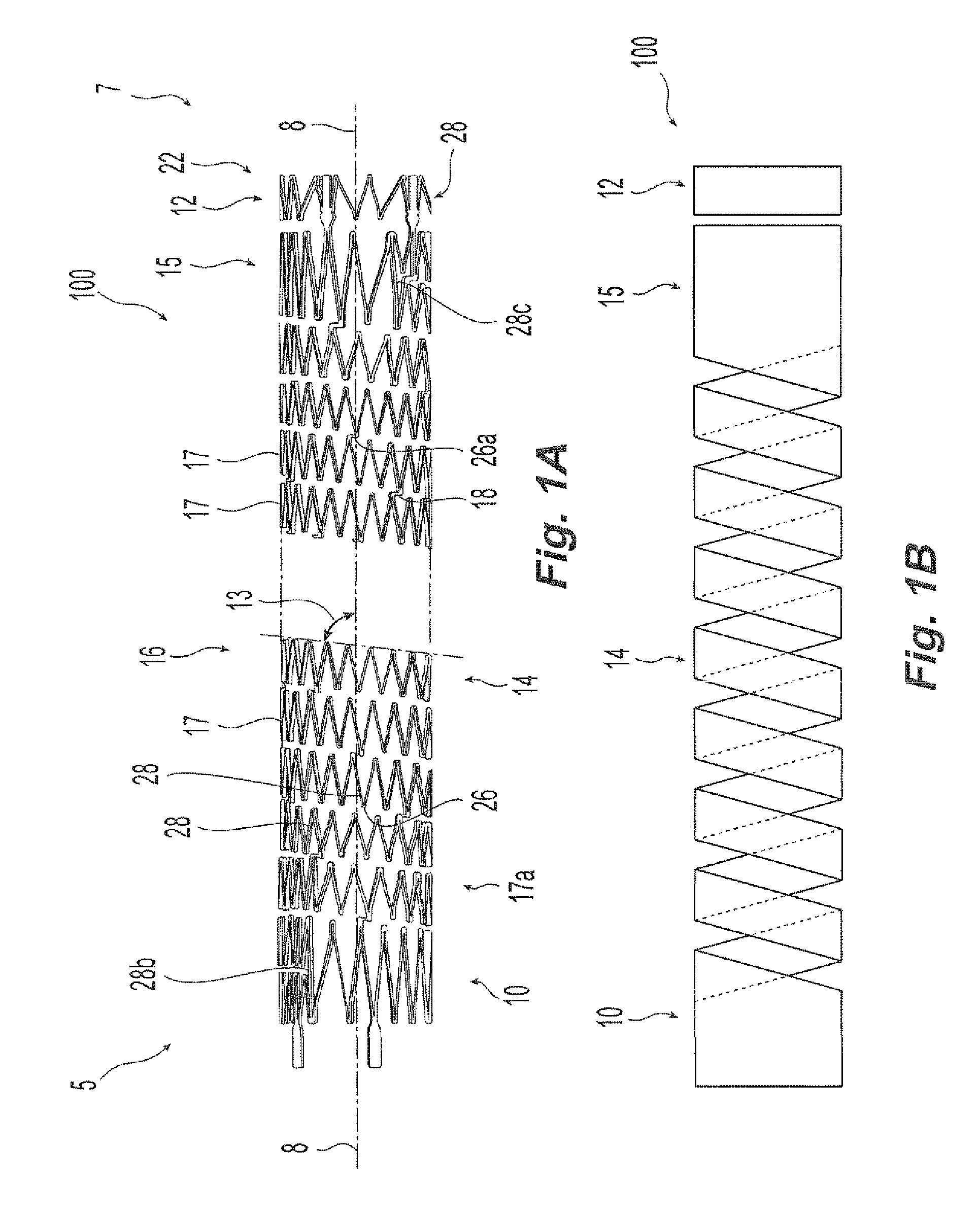
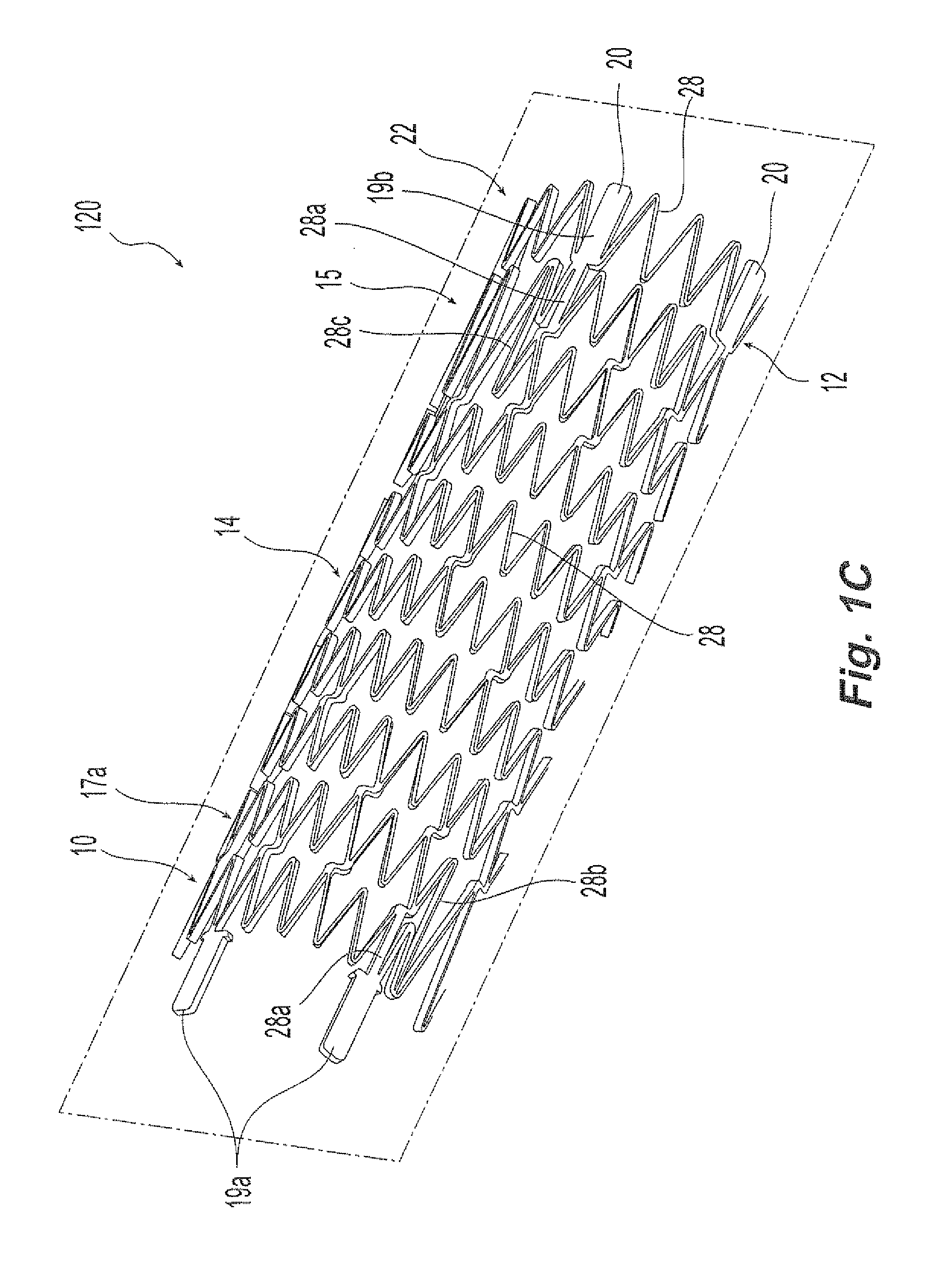
[0030]The following detailed description should be read with reference to the drawings, in which like elements in different drawings are identically numbered. The drawings, which are graphical representations and not necessarily to scale, depict selected embodiments and are not intended to limit the scope of the invention. The detailed description illustrates by way of example, not by way of limitation, the principles of the invention. This description will clearly enable one skilled in the art to make and use the invention, and describes several embodiments, adaptations, variations, alternatives and uses of the invention, including what is presently believed to be the best mode of carrying out the invention.

[0031]As used herein, the terms “about” or “approximately” for any numerical values or ranges indicate a suitable dimensional tolerance that allows the part or collection of components to function for its intended purpose as described herein. Also, as used herein, the terms “pat...


PUM


Abstract

Preferred embodiments of an implantable medical device with a high degree of flexibility is shown and described. One aspect includes an implantable stent having an intermediate portion with a helical winding and first and second end portions. The implantable stent further includes a coupling portion with a helical winding, and bridges joining struts of defining the helical windings. The stent also includes a paddle providing a bridge joining the ends or the helical windings. Another aspect relates to a radially self-expansible stent with a plurality of radiopaque markers attached to it. The markers are shaped and located at the stent end such that the compressive stress exerted on the end annulus of the stent during release of the stent is shared between the markers and the inflection zones that do not carry a marker.

Description

RELATED APPLICATIONS[0001]This application claims benefit of priority to U.S. Provisional Patent Application No. 60 / 842,853 filed Sep. 7, 2006 which is incorporated by reference in its entirety.BACKGROUND[0002]It is known in the medical field to utilize an implantable prosthesis to support a duct or vessel in a mammalian body. One such prosthesis may include a frame-like structure. Such frame-like structures are commonly known as a “stent”, “stent-graft” or “covered stent.” These structures are referred to collectively herein as a “stent”, “implant”, or an “implantable prosthesis.”[0003]The stent or prosthesis can be utilized to support a duct or vessel in the mammalian body that suffers from an abnormal widening (e.g., an aneurysm, vessel contraction or lesion such as a stenosis or occlusion), or an abnormal narrowing (e.g., a stricture). Stents are also utilized widely in the urethra, esophagus, biliary tract, intestines, arteries, veins, as well as peripheral vessels. The stent c...

Claims


Application Information

Patent Timeline
IPC IPC(8): A61F2/06
CPCA61F2/88A61F2/91A61F2/915A61F2/966A61F2002/91508A61F2230/0054A61F2002/91525A61F2002/91533A61F2002/91558A61F2002/91566A61F2250/0098A61F2002/91516
Inventor ZIPSE, ACHIMBLOCK, ANDREASWEISE, PAULINESCHLUN, MARTIN
Owner CR BARD INC
Why Eureka
Try Eureka