Exhaust System

a technology of exhaust system and flange connection, which is applied in the direction of stators, machines/engines, transportation and packaging, etc., can solve the problems of increasing thermal problems, increasing thermal problems, and increasing thermal problems, so as to increase the service life or lifespan of thermal loads, and increase thermal stability and strength.

Active Publication Date: 2010-01-14
PUREM GMBH
View PDF48 Cites 15 Cited by
  • Summary
  • Abstract
  • Description
  • Claims
  • Application Information

AI Technical Summary

Benefits of technology

[0006]Embodiments of the present invention deal with the problem to state an improved embodiment for an exhaust system or for a flange connection of the type mentioned at the ...

Problems solved by technology

In exhaust systems or in other systems conducting hot gases there is the problem in the region of flange connections that the flange connection is exposed to a relatively high thermal load.
The thermal problems are amplified when for the sake of costs and/or for the sake of weight thinner and/or simpler materials of...

Method used


Image

  • Exhaust System
  • Exhaust System
  • Exhaust System

Examples


Embodiment Construction

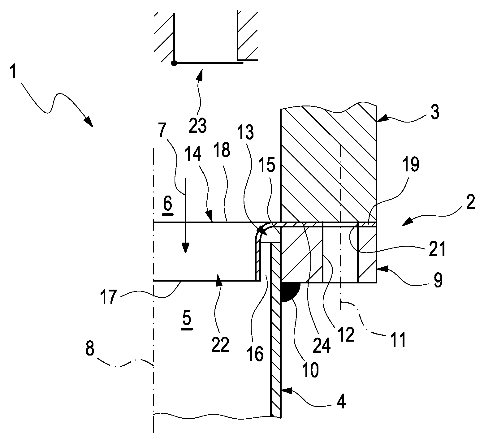
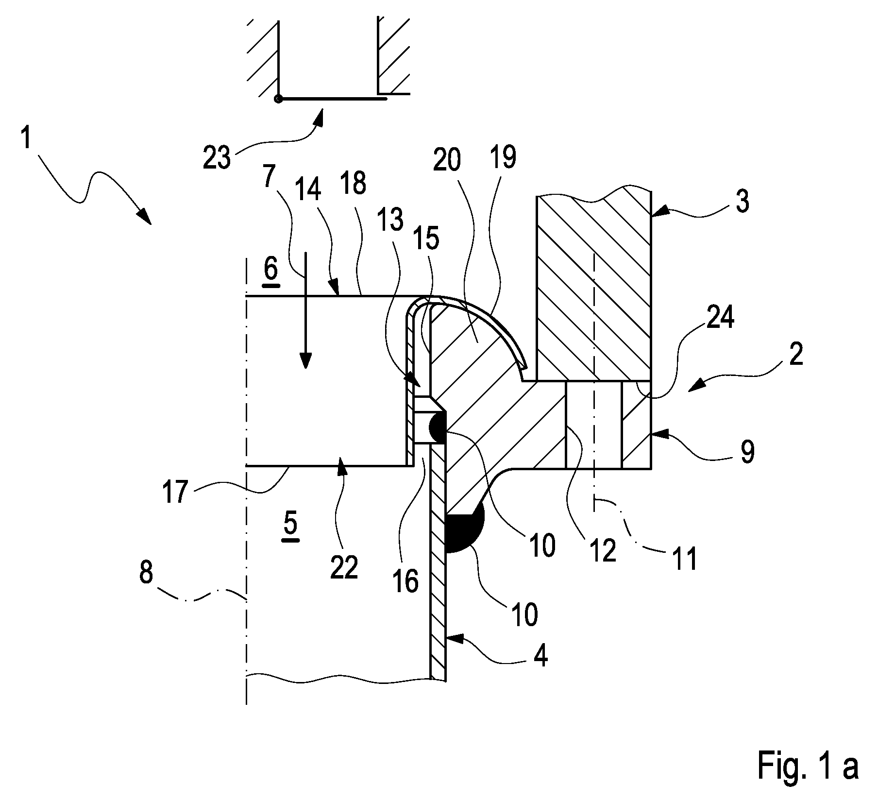
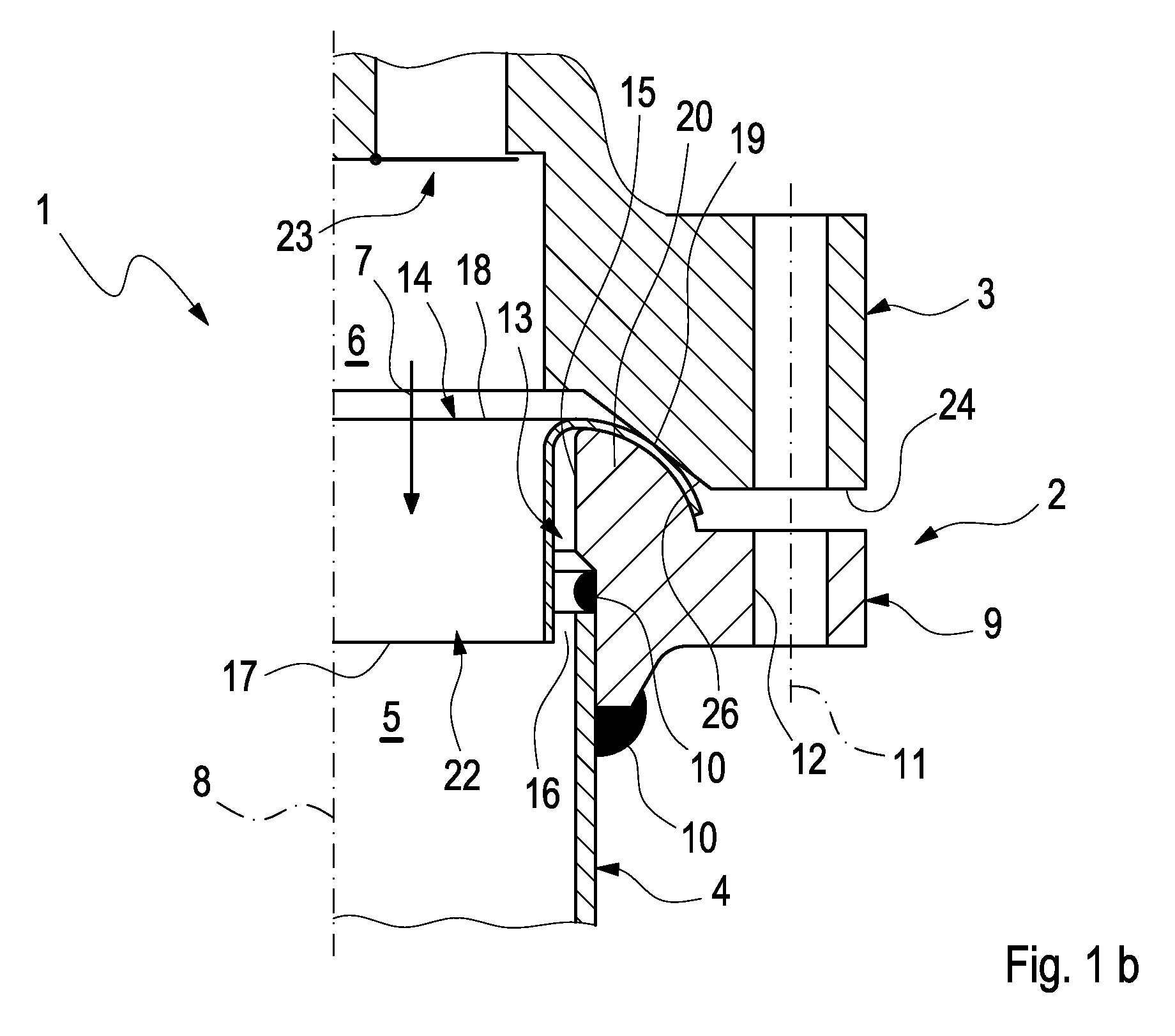
[0020]According to FIGS. 1 to 3 an exhaust system 1 shown only partly comprises at least one flange connection 2. The flange connection 2 in this case serves for the connecting of two components. In the present case that is for connecting two components of the exhaust system 1. A first component 3 in the case of the exhaust system 1 for example is an exhaust gas turbine which in the following is likewise designated exhaust gas turbine 3. Only a part of a housing is shown of the exhaust gas turbine 3. In addition, a waste gate valve 23, which can be optionally present, is indicated symbolically.

[0021]A second component 4 for example is a tubular component 4. In the case of the exhaust system 1 this is practically an exhaust pipe which in the following is likewise designated exhaust pipe 4. It can also be a funnel. The exhaust system 1 serves to discharge exhaust gases of an internal combustion engine which more preferably can be located in a motor vehicle. The exhaust gas turbine 3 s...


PUM


Abstract

The present invention relates to an exhaust system for an internal combustion engine, more preferably of a motor vehicle, with an exhaust gas turbine, with an exhaust pipe, whose inlet is fluidically connected with an outlet of the exhaust gas turbine, with a flange connection for connecting the exhaust gas turbine with the exhaust pipe which comprises a flange fastened to the exhaust pipe and attached to the exhaust gas turbine, and with a shielding apron which is so arranged and/or incorporated in the flange connection that in the operation of the exhaust system it protects a transition region between the flange and the exhaust pipe from direct admission of exhaust gas.

Description

CROSS-REFERENCE TO RELATED PATENT APPLICATIONS[0001]This patent application claims the benefit of co-pending German Patent Application No. DE 102008031887.6, filed on Jul. 8, 2008, the entire teachings and disclosure of which are incorporated herein by reference thereto.FIELD OF THE INVENTION[0002]The present invention relates to an exhaust system for an internal combustion engine, more preferably a motor vehicle. The invention also relates to a flange connection between a first component and a second component.BACKGROUND OF THE INVENTION[0003]In exhaust systems or in other systems conducting hot gases there is the problem in the region of flange connections that the flange connection is exposed to a relatively high thermal load. This is true more so when it concerns a built flange connection, wherein a separately manufactured flange is attached to a tubular component. Forming the flange connection, this component can then be attached to another component with the help of the flange...

Claims


Application Information

Patent Timeline
IPC IPC(8): F01N5/04F16L59/16
CPCF01D9/023F01D25/243F02B39/00F01N13/1827F01N13/085
Inventor FINKBEINER, GOTZMULLER, JORG-UWEWIRTH, GEORG
Owner PUREM GMBH
Why Eureka
Try Eureka