Method and apparatus for sealing abandoned oil and gas wells

Inactive Publication Date: 2010-01-14
SPENCER HOMER L
View PDF6 Cites 46 Cited by
  • Summary
  • Abstract
  • Description
  • Claims
  • Application Information

AI Technical Summary

Problems solved by technology

Such leakage can have adverse consequences from unpleasant smells and site contamination to creating a possibly latent explosive condition or the release of a toxic gas such as hydrogen sulfide.
Many operations may occur underground at depths considerably below the six

Method used


Image

  • Method and apparatus for sealing abandoned oil and gas wells
  • Method and apparatus for sealing abandoned oil and gas wells
  • Method and apparatus for sealing abandoned oil and gas wells

Examples


Embodiment Construction

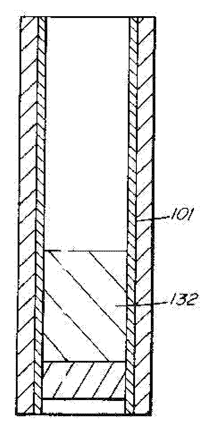
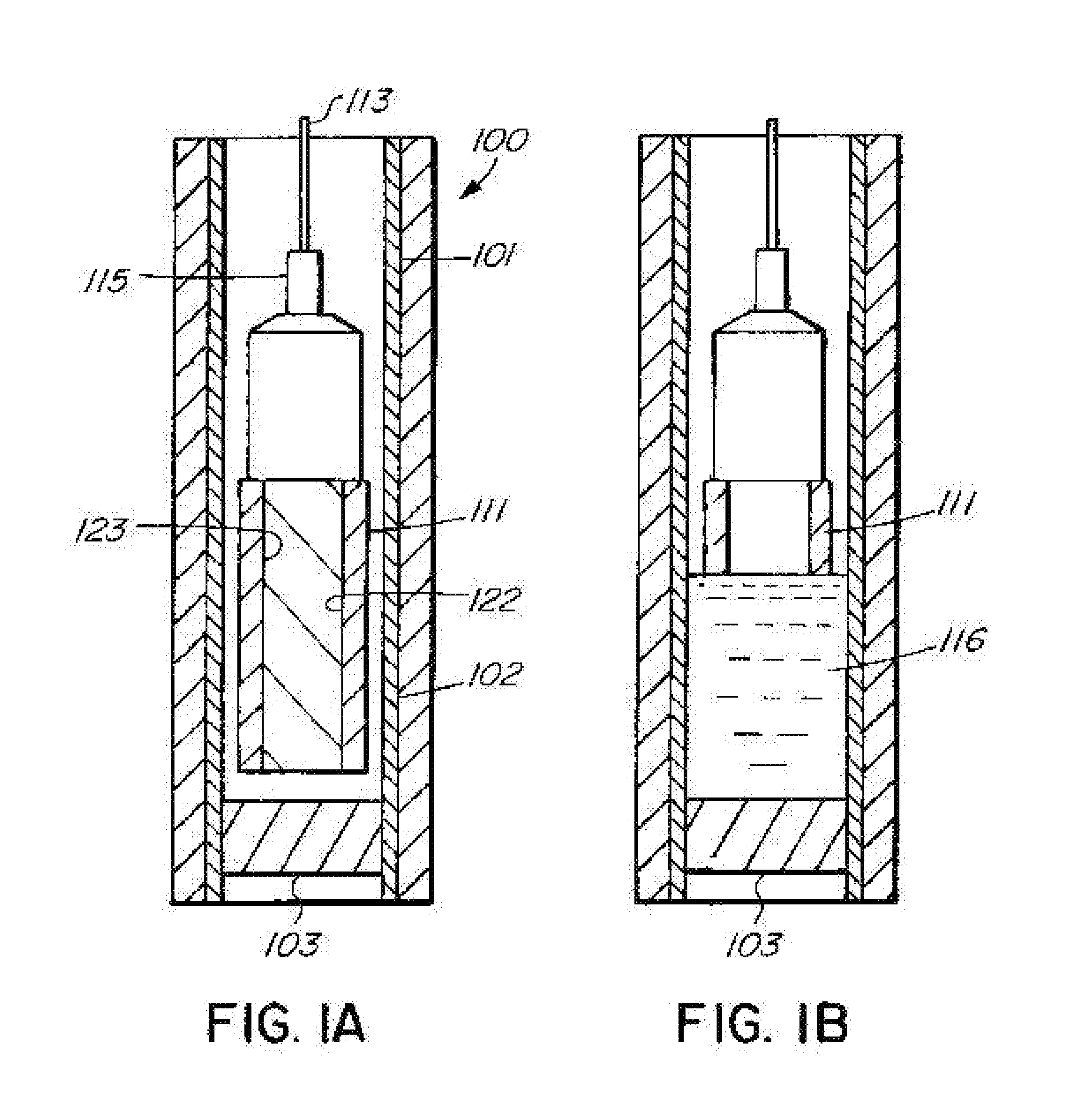
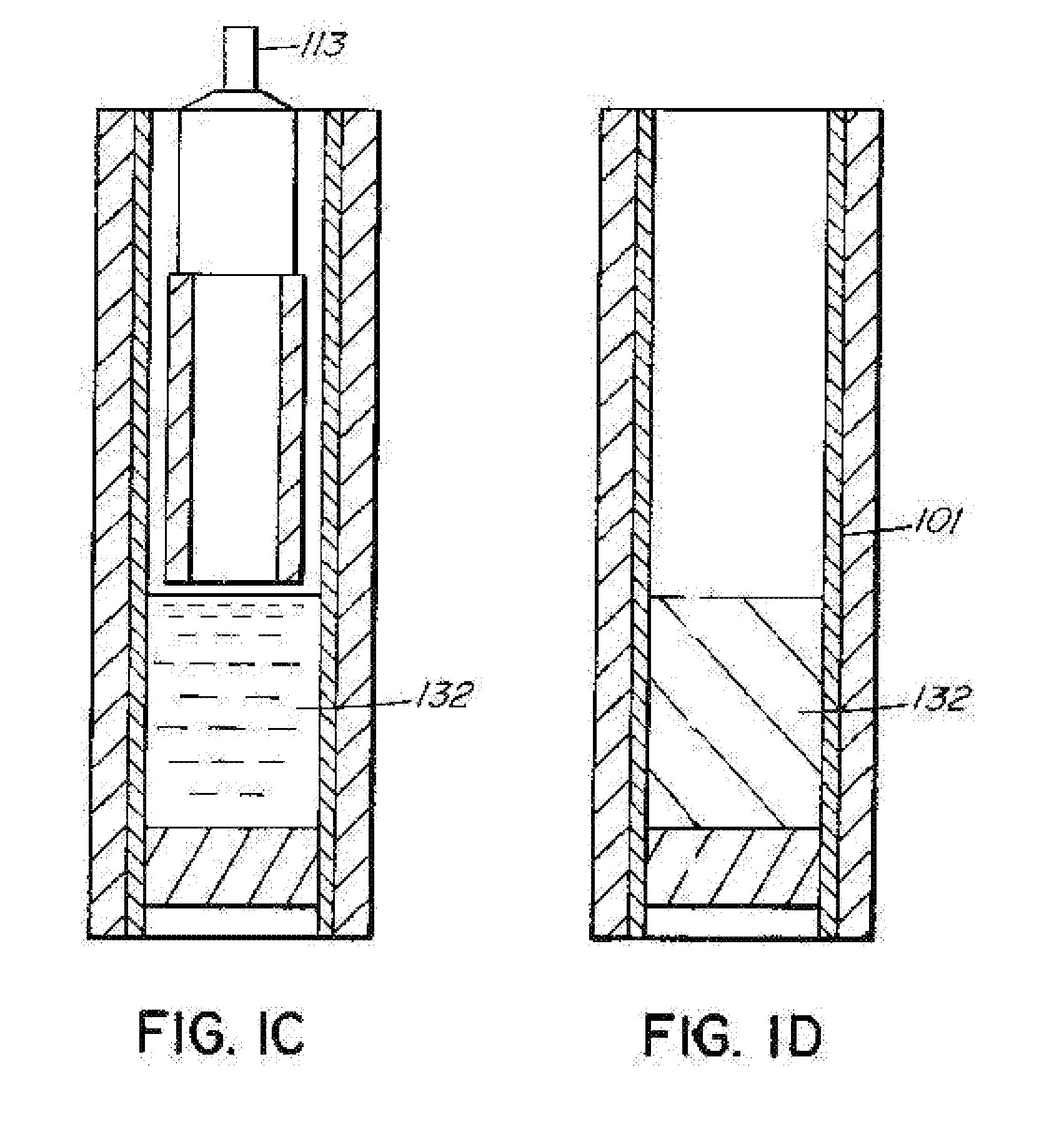
[0016]Referring now to the drawings, an oil or gas well is shown generally in enlarged form at 100 in FIG. 1. It comprises production casing illustrated generally at 101 which is cemented in and surrounded with cement 102. A solid cement plug 103 is illustrated in place at the position of interest within the production casing 101. The setting and formation of the cement plug 103 is well known in the art.

[0017]The components generally used for setting and forming the bismuth-tin alloy plug are best illustrated in FIG. 2. Such components comprise a power control unit 104 located on the surface 114 which also serves as the source of input power, generally 480 volt three-phase alternating current which is subsequently rectified to adjustable voltage DC current for transmission to a heating tool 111. The required power connections 105 are connected to a wireline spool 110 and extend from the spool 110 downhole by way of wireline cables 113 to an attachment 115 of the heating tool 111 whi...


PUM


Abstract

Apparatus and method for forming a solid sealing plug of bismuth-tin alloy material within a well casing for sealing oil or gas wells. Solid alloy material is positioned within a heating tool and lowered to a position within the well casing where the seal is to be formed. The heating tool is heated to liquefy the alloy material and the alloy material then runs out of the heating tool and solidifies on top of a cement plug previously formed within the well casing. A cement slurry or other fluid material may subsequently be deposited on top of the liquefied alloy material to enhance the sealing of the alloy plug, to form a barrier to subsequent creep of the alloy plug when the alloy solidifies and to counteract any pressure acting vertically on the bottom of the plug.

Description

CROSS-REFERENCE TO RELATED APPLICATION[0001]This application claims the benefit of provisional patent application Ser. No. 61 / 052,999 filed May 13, 2008.INTRODUCTION[0002]This invention relates to a method and apparatus for sealing abandoned oil and gas wells and, more particularly, to sealing abandoned oil and gas well utilising an eutectic alloy which expands upon passage from the liquid to solid state.BACKGROUND OF THE INVENTION[0003]When oil and gas wells are shut in or abandoned, a regulatory framework exists which mandates the procedures and technology required to properly shut in or abandon the well. This is required to prevent so far as is possible the leakage of gas from the underground formations to the surface. Such leakage can have adverse consequences from unpleasant smells and site contamination to creating a possibly latent explosive condition or the release of a toxic gas such as hydrogen sulfide.[0004]Heretofore, following the addition of cement to the production an...

Claims


Application Information

Patent Timeline
IPC IPC(8): E21B33/13E21B33/12
CPCE21B33/1208E21B36/04E21B33/13
Inventor SPENCER, HOMER L.
Owner SPENCER HOMER L
Why Eureka
Try Eureka