Ion implantation apparatus and ion implantation method

Inactive Publication Date: 2010-01-14
SUMCO CORP
View PDF6 Cites 6 Cited by
  • Summary
  • Abstract
  • Description
  • Claims
  • Application Information

AI Technical Summary

Benefits of technology

[0025]As a result of study by the inventors, it was found that it is preferable to provide an angle of inclination of 5° or more in order to have satisfactory holding conducted by the holding pins. When the angle of incidence of the ion beam is less than 5° while an angle of inclination enabling satisfactory holding is provided, a protruding portion is produced wherein the second holding pin blocks the ion beam, and pin marks are created in the wafer after ion implantation. Moreover, it is unsuitable when the inclination of the wafe

Problems solved by technology

Consequently, when the holding pins of resin manufacture soften in a he

Method used


Image

  • Ion implantation apparatus and ion implantation method
  • Ion implantation apparatus and ion implantation method
  • Ion implantation apparatus and ion implantation method

Examples


Embodiment Construction

[0043]The ion implantation apparatus of an embodiment of the present invention is described below with reference to FIG. 1A to FIG. 8. Here, the ion implantation apparatus of the present embodiment is described as one which uses the SIMOX method to fabricate a SOI substrate by implanting oxygen ions into a silicon wafer. In all of the following drawings, the layer thicknesses and dimensional proportions of each component element are suitably varied in order to facilitate viewing of the drawing.

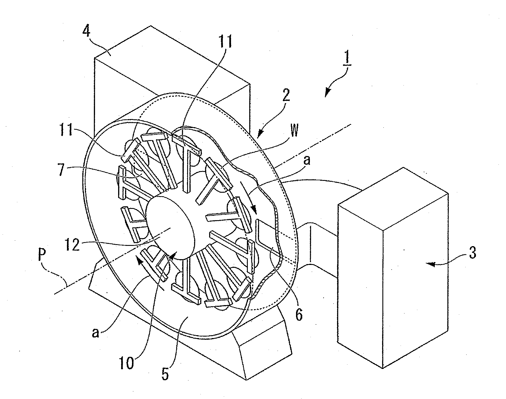
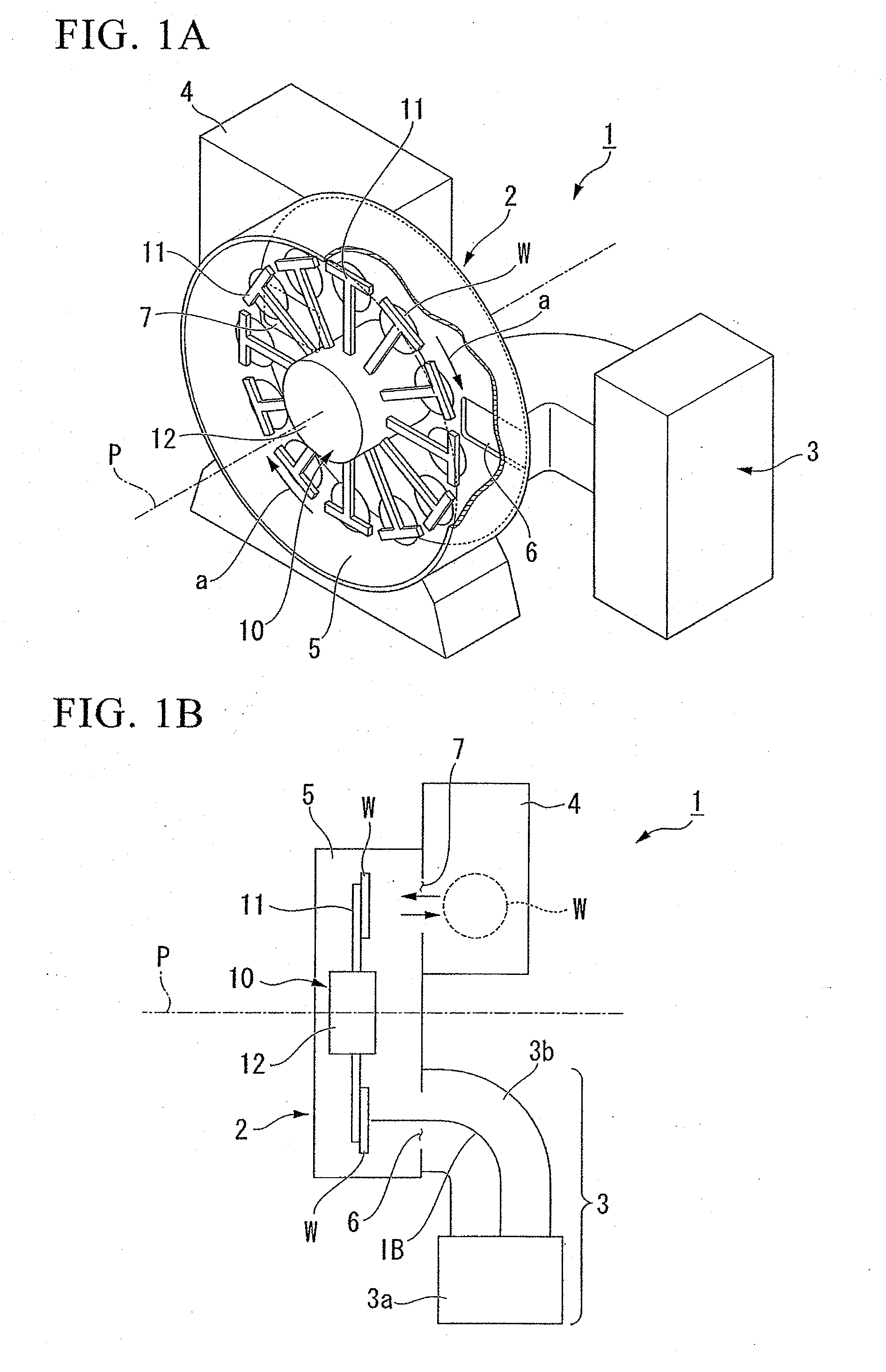
[0044]FIG. 1A and FIG. 1B are diagrams which show an ion implantation apparatus 1 of the present embodiment. FIG. 1A is a perspective view, and FIG. 1B is a schematic drawing which shows the operation of the ion implantation apparatus 1.

[0045]As shown in FIG. 1A, the ion implantation apparatus 1 is provided with an ion implanter 2 which conducts ion implantation relative to a wafer W, an ion beam generator 3 which generates the ion beam that irradiates the wafer W, and a wafer conveyor 4 which...


PUM


Abstract

This ion implantation apparatus is provided with a holding devise which holds the wafer, and which turns it along its circumference. In addition to holding the wafer at a prescribed position, the ion implantation apparatus subjects the wafer to ion implantation in regions where there is partial overlap of its circumference. The holding devise turns and inclines the wafer, and also holds the wafer by three or more holding pins. The side face of the holding pin has an inversely tapered shape, and the multiple holding pins include a first holding pin whose protrusion amount is relatively small, and a second holding pin whose protrusion amount is relatively large. The holding pin which is on the upper side from the center of the wafer in the planar direction of the inclined wafer is the second holding pin, and the angle of inclination of the side face of the second holding pin at a position where ions are implanted into the wafer has an angular degree which is equal to or less than an angle of incidence of the ion beam relative to the wafer.

Description

BACKGROUND OF THE INVENTION[0001]1. Field of the Invention[0002]The present invention relates to an ion implantation apparatus which implants ions into substrates such as silicon wafers, and in particular to an ion implantation apparatus and ion implantation method which combine prevention of wafer droppage in replacement operations and inhibition of pin mark occurrence.[0003]Priority is claimed on Japanese Patent Application No. 2008-173621, filed Jul. 2, 2008, the content of which is incorporated herein by reference.[0004]2. Description of Related Art[0005]From the standpoint of fabrication of semiconductor devices which have high speed and low power consumption, SOI (Silicon on Insulator) substrates are the focus of attention. SOI substrates have embedded oxide film with excellent insulation properties, and a thin silicon layer (SOI layer) which covers this. In SOI substrates, this silicon layer is used as the active layer, thereby enabling achievement of semiconductor devices wi...

Claims


Application Information

Patent Timeline
IPC IPC(8): H01J37/20
CPCH01J37/20H01J2237/20214H01J2237/2007H01J37/3171
Inventor AOKI, YOSHIRO
Owner SUMCO CORP
Why Eureka
Try Eureka