
Method of lighting gas discharge lamp

Inactive Publication Date: 2010-01-14
ARCLITE OPTRONICS CORP
View PDF0 Cites 4 Cited by
  • Summary
  • Abstract
  • Description
  • Claims
  • Application Information

AI Technical Summary

Benefits of technology

[0007]A novel method of lighting a gas discharge lamp is disclosed herein. A major purpose of the present invention is to grow tips evenly on the two electrodes of the gas discharge lamp so that the distance between the electrodes is maintained or even reduced, and the stability of the electric arc is enhanced. Another major purpose of the present invention is that the method is applicable to both a LCD projection system and a DLP projection system.
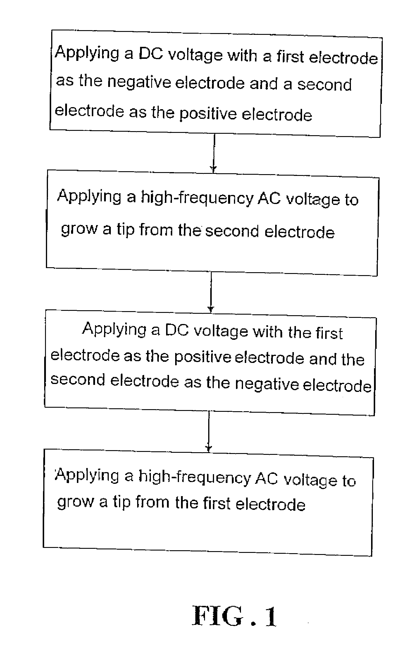
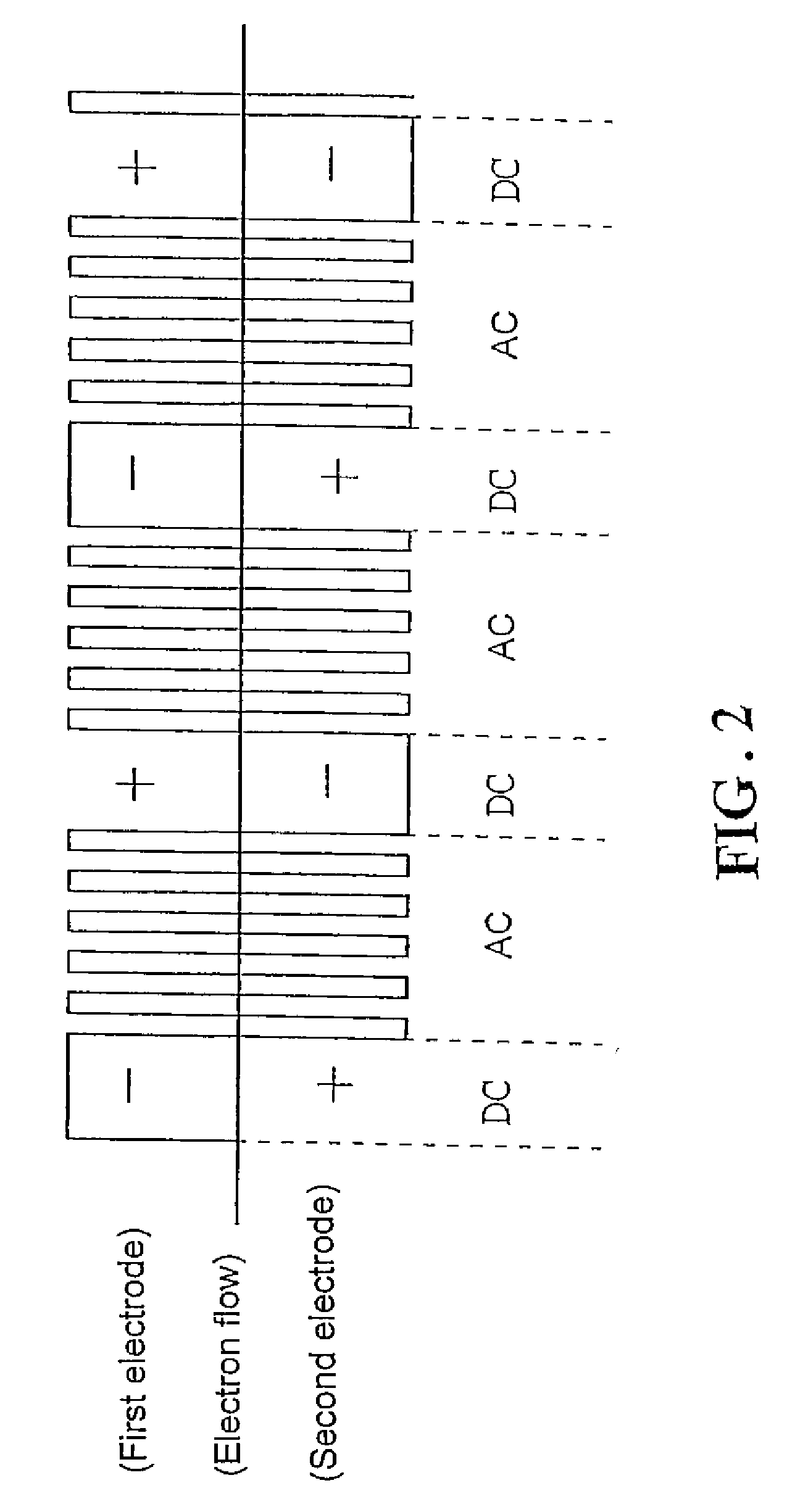
[0009]Based on the foregoing principle, The method first applies a direct-current (DC) voltage to light the gas discharge lamp with a first electrode of the gas discharge lamp being the negative electrode and a second electrode as the positive electrode. As the temperature of an arc spot of the second electrode rises to a certain temperature, the method then removes the DC voltage and applies a high-frequency, alternating-current (AC) voltage to light the gas discharge lamp. Since the temperature of the second electrode's arc spot is high enough, the arc spot would be the electron emission point when the second electrode functions as the negative electrode during the application of the AC voltage. After the AC voltage is applied for a period of time and the temperature of the second electrode is not high enough to maintain a stable arc spot the method removes the AC voltage and applies a DC voltage again but with the first electrode as the positive electrode and the second electrode as the negative electrode. The method repeats the foregoing process and, as the tungsten ions in the electric arc are steadily deposited on the arc spots of the electrodes alternately and two tips are thereby evenly developed on the first and second electrodes, respectively. As such, the distance between the first and second electrodes is well under control and the stability of the electric arc is significantly improved.

Problems solved by technology

However, as the material used for the electrodes would evaporate under the high temperature of the electric arc, the distance between the electrodes would gradually increase as the gas discharge lamp is put to use.
The reason is that the latter has compatibility issues with the rotational speeds of the color wheel and the micromirrors of the Digital Micromirror Device (DMD) chip, and a stable lighting frequency is required.

Method used


Image

  • Method of lighting gas discharge lamp
  • Method of lighting gas discharge lamp
  • Method of lighting gas discharge lamp

Examples


Embodiment Construction

[0014]The following descriptions are exemplary embodiments only, and are not intended to limit the scope, applicability or configuration of the invention in any way. Rather, the following description provides a convenient illustration for implementing exemplary embodiments of the invention. Various changes to the described embodiments may be made in the function and arrangement of the elements described without departing from the scope of the invention as set forth in the appended claims.

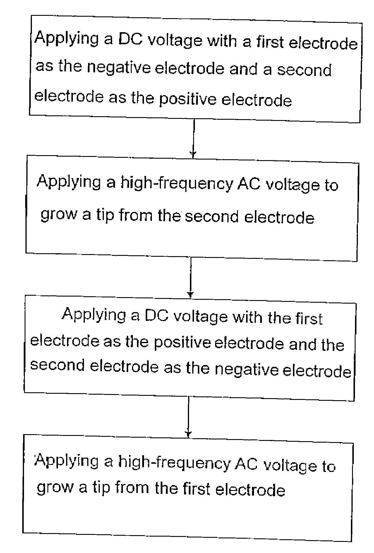
[0015]FIG. 1 is a flow diagram showing the steps of lighting a gas discharge lamp according to the present invention. The method first applies a DC voltage to light the gas discharge lamp with a first electrode of the gas discharge lamp being the negative electrode and a second electrode as the positive electrode. As the temperature of an arc spot of the second electrode (i.e., positive electrode) rises to a certain temperature, the method then removes the DC voltage and applies a high-frequency AC ...


PUM


Abstract

The present invention lights a gas discharge lamp with a stable average frequency and in the mean time grows tips evenly on the two electrodes of the gas discharge lamp so that the distance between the electrodes is maintained and the stability of the electric arc is enhanced. The present invention first applies a DC voltage and then a high-frequency AC voltage to the electrodes of the gas discharge lamp. The present invention then applies a reversed DC voltage and then a high-frequency AC voltage to the electrodes. This process is repeated and, as the tungsten ions in the electric arc are steadily deposited on the arc spots of the electrodes alternately and two tips are thereby evenly developed on the first and second electrodes, respectively.

Description

(a) TECHNICAL FIELD OF THE INVENTION[0001]The present invention generally relates to gas discharge lamps, and more particularly to a method of lighting a gas discharge lamp capable of producing a more stable electric arc.(b) DESCRIPTION OF THE PRIOR ART[0002]For a gas discharge lamp, a shorter distance between the electrodes would contribute to a more stable electric arc. However, as the material used for the electrodes would evaporate under the high temperature of the electric arc, the distance between the electrodes would gradually increase as the gas discharge lamp is put to use. For example, the electrodes of an Ultra High Performance (UHP) mercury lamp commonly found in a modem projector are often made of tungsten, which is well-known for its high melting point and low vapor pressure. Even as such, the tungsten electrodes of an UHP mercury lamp would still suffer the fast evaporation described above. The increased distance between the electrodes would contribute to a higher ope...

Claims


Application Information

Patent Timeline
IPC IPC(8): G09G3/00
CPCH05B41/2928
Inventor FENG, HUI-HSIANGYEH, YA-CHUAN
Owner ARCLITE OPTRONICS CORP
Learn More