Torquer Apparatus

a technology of torquer and torquer, which is applied in the direction of single motor speed/torque control, dynamo-electric machines, synchronous motor starters, etc., can solve the problems of total momentum, force the wheels or the sphere to spin at their maximum angular velocity, and not available as commercial products, so as to achieve excellent efficiency.

Inactive Publication Date: 2010-01-14
CSEM CENT SUISSE DELECTRONIQUE & DE MICROTECHNIQUE SA RECH & DEV
View PDF16 Cites 8 Cited by
  • Summary
  • Abstract
  • Description
  • Claims
  • Application Information

AI Technical Summary

Benefits of technology

[0008]Alternatively, the bearing of the sphere can be a reluctant magnetic bearing such as disclosed in U.S. Pat. No. 4,611,863 or U.S. Pat. No. 4,961,352. In this case, as there is no contact with the sphere, to be actuated, the sphere has to become the rotor of a 3D motor. No contact with the sphere is advantageous, because it means lower vibrations, higher reliability, and longer lifetime. Three orthogonal pairs of arced linear inductive motors (U.S. Pat. No. 4,611,863) or three orthogonal pairs of ring inductive motors (U.S. Pat. No. 4,961,352) are used to control the bearing and the rotation of the rotor. Even though elegant, such motors are unfortunately highly inefficient, which is a problem of important concern in space. The principle of inductive motor is to drag the rotor thanks to a moving field exerting a ‘magnetic friction’. As a consequence, the magnetic friction checks any motions of the rotor that are not following the direction of the moving field. In other words, the rotation created by one pair of inductive motors is checked by the two other pairs, dissipating thermal energy in the rotor.
[0016]The invention allows the construction of an efficient reaction-gyro sphere with magnetic bearing. Any rotation is possible at any time and the rotor is perfectly isotropic regarding its dynamic properties. One reaction-gyro sphere is enough to control the attitude of a vehicle. In addition, as the rotor has a constant source of magnetic field, on the one hand, the system is linear, allowing the decoupling of the motor and bearing functions by simple superposition, and on the other hand, the efficiency is potentially excellent with even the possibility to recover the kinetic energy stored in the rotor.

Problems solved by technology

Reaction-gyro spheres have also been proposed (see, for instance, U.S. Pat. No. 4,611,863), but are not available as commercial products.
In some situations, the external torques may eventually significantly alter the total momentum, forcing the wheels or the sphere to spin at their maximum angular velocity.
Some rotations are impossible with a single control moment gyroscope.
Even though elegant, such motors are unfortunately highly inefficient, which is a problem of important concern in space.

Method used


Image

  • Torquer Apparatus
  • Torquer Apparatus
  • Torquer Apparatus

Examples


Embodiment Construction

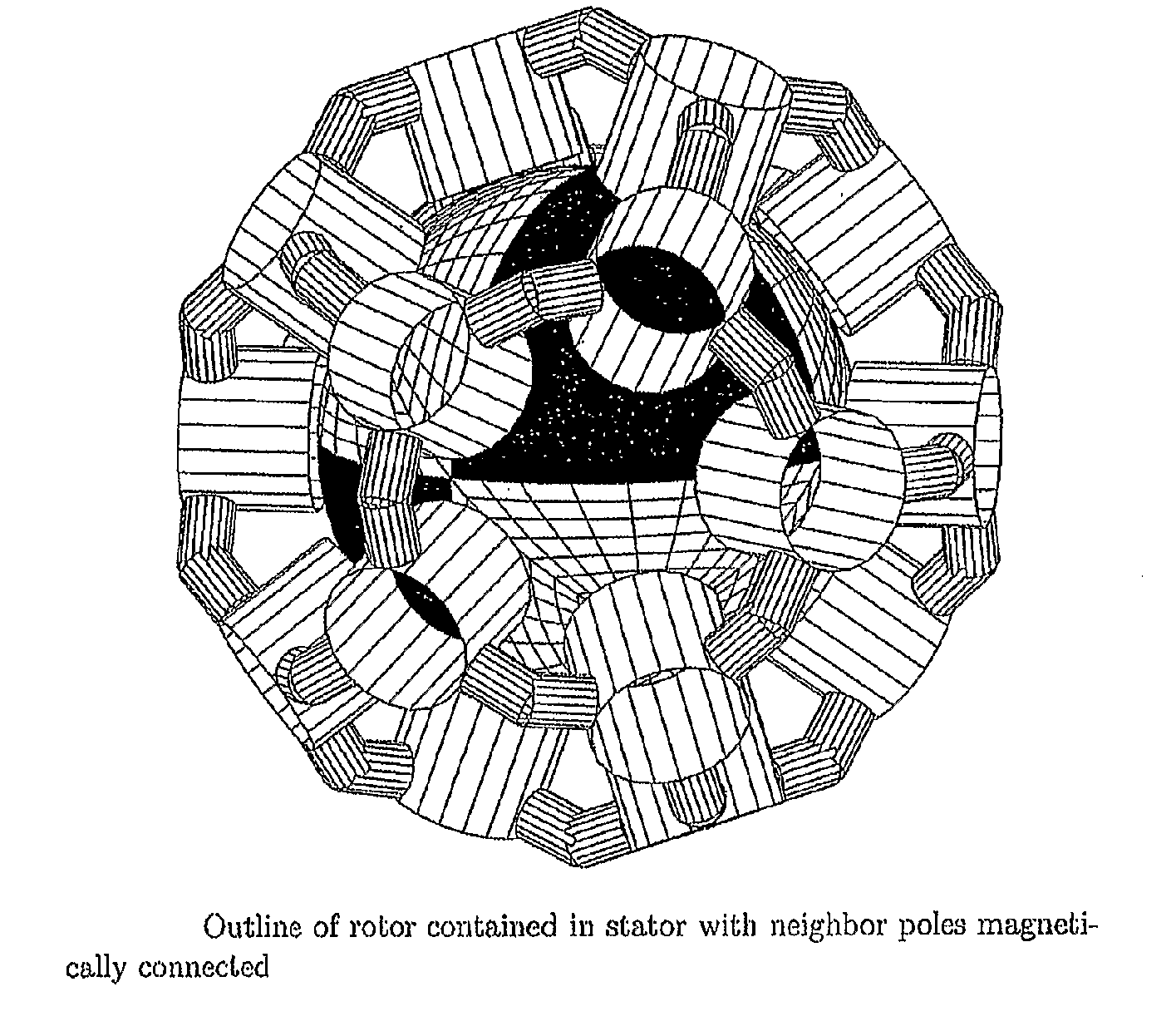
[0022]The reaction-gyro sphere may consist of a nominally concentric assembly of an essentially spherical rotor and an essentially spherical stator. As far as the dynamic is concerned, the stator may actually be part of the vehicle body. The apparatus is also called a torquer, since its function is to export torque to the vehicle. As a reaction to the exported torque, the vehicle momentum is changed and the attitude eventually controlled.

[0023]For a large vehicle, the rotor is usually contained in the stator. To increase the rotor moment of inertia without increasing weight, the rotor can be made hollow. For a small vehicle, like an agile satellite, the opposite arrangement may be considered, i.e., with the stator (and the vehicle) contained in the rotor. In this case, the rotor may have to be designed such as to show large open portions, so as not to disturb significantly the satellite functions requiring access to the external space.

[0024]As opposed to U.S. Pat. No. 5,798,590 pate...


PUM


Abstract

A torquer apparatus generally comprises a reaction-gyro sphere consisting of a concentric assembly of a substantially spherical rotor and a substantially spherical stator. This is implemented in the present invention as a rotor with magnetic poles such that, when radially projected on a concentric octahedron, the same symmetrical pattern is obtained on all faces of said octahedron, the polarity of the poles projected on two adjacent faces of said octahedron being opposite and a stator with at least twenty poles magnetized with coils and such that, when radially projected on a concentric icosahedron, the same symmetrical pattern is obtained on all faces of said icosahedron, said stator being-in nominal position-concentric with said rotor. Real-time measurements, or equivalent information, of the position of the rotor with respect to the stator are obtained together with exported torque from the stator, or the orientation of the rotor with respect to the stator. A controller controls the current in the coils of the stator poles based on said measurements, or said equivalent information, such that the rotor is magnetically held in said nominal position, and that the desired torque is exported.

Description

[0001]The invention relates to torquer apparatus.[0002]An accepted way to control the attitude of a vehicle in space is the use of reaction wheels or control moment gyroscopes. Reaction-gyro spheres have also been proposed (see, for instance, U.S. Pat. No. 4,611,863), but are not available as commercial products.[0003]The three approaches are based on the principle that the total momentum of a cluster of mobile bodies is constant when no external torque is applied. Thus, a change of the momentum of one body, e.g., a wheel or a sphere, implies an opposite change of the momentum of the other bodies, e.g., the vehicle. As the momentum is the product of the moment of inertia with the angular velocity, a change of momentum results in a change of angular velocity. The attitude of the vehicle can therefore be controlled using these approaches, despite changes of momentum caused by moving parts of instruments, and despite external torques, caused, for example, by the Earth's magnetic field ...

Claims


Application Information

Patent Timeline
Patent Type & Authority Applications(United States)
IPC IPC(8): H02K1/27H02K1/12H02P6/18H02K29/10H02P6/08
CPCB64G1/28G01C19/30H02K16/00Y10T74/1254H02K41/031H02K2201/18H02K2201/03H02K21/12
Inventor CHETELAT, OLIVIER
Owner CSEM CENT SUISSE DELECTRONIQUE & DE MICROTECHNIQUE SA RECH & DEV
Why Eureka
Try Eureka