Tone Wheel

a technology of a wheel and a cylinder head, which is applied in the direction of magnets, magnetic bodies, instruments, etc., can solve the problems of deteriorating the detection accuracy of magnetic sensors, increasing waste materials, and unable to reuse molding, so as to achieve reliable rotation detection, less damage, and the effect of keeping measurement accuracy

Inactive Publication Date: 2010-01-14
UCHIYAMA MFG
View PDF12 Cites 12 Cited by
  • Summary
  • Abstract
  • Description
  • Claims
  • Application Information

AI Technical Summary

Benefits of technology

[0013]According to the tone wheel of the first aspect of the present invention, the circular multipolar magnet is made of a plastic magnet, so that the surface to be detected is less damaged or peeled off when foreign materials are bit between the magnet and the magnetic sensor comparing with the case using a circular rubber magnet, thereby keeping measurement accuracy. Further, the circular multipolar magnet is fixedly integrated to the metal reinforcing ring by means of adhesive and a restraint portion as set forth in the second to the fifth aspects of the present invention is provided for a part of the fixed and integrated portion. The fixed and integrated condition by the adhesive is accordingly reinforced, so that the circular multipolar magnet does not come off when being used under a hard environment such as a detection part for the wheel rotation of automobile where foreign materials such as water, dirt and dust scatter, thereby achieving reliable rotation detection.
[0014]Further, the circular multipolar magnet is a plastic magnet made of a circular resin molded product including a magnetic powder magnetized by providing a number of S and N poles alternatively in the circumferential direction. As the result, the fluidity of the magnetic powder is high in the resin material when the magnetic powder is oriented by applying a magnetic filed at the time of molding (for example, injection molding), thereby achieving a high orientation efficiency and obtaining a circular multipolar magnet with superior magnetic characteristic by being magnetized after molding. The fluidity of the magnetic powder in an unvulcanized rubber material in case of a magnetic rubber is inferior than that of the resin material, so that much magnetic powder is required to increase the magnetic characteristic or the magnetic powder is required to be oriented by applying a strong magnetic field. In addition, if the resin binder is made of a thermoplastic resin, the flash produced at the time of molding can be reused, thereby contributing to improve the process yield of the used material.
[0015]Still further, when there exist protrusions of the adhesive at an end of the fixed and integrated portion of the circular multipolar magnet and the metal reinforcing ring by means of adhesive as set forth in the sixth aspect of the present invention, water is prevented from coming in the adhesion boundary surfaces by the existence of the protrusions, thereby eliminating breakage of the circular multipolar magnet when the invaded water is frozen.

Problems solved by technology

However, when the tone wheel is used for detecting the rotation of automobile wheel, it is apt to be used in a hard circumstances where foreign materials such as water, dirt, and dust scatter, so that such foreign materials are bit between the circular multipolar magnet being a circular rubber magnet and the magnetic sensor to make the surface to be detected of the circular multipolar magnet peeled off, damaged or broken, thereby deteriorating the detection accuracy of the magnetic sensor.
The flash caused at the time of molding cannot be reused because the rubber material is vulcanized, thereby increasing waste material.

Method used


Image

  • Tone Wheel
  • Tone Wheel
  • Tone Wheel

Examples


embodiment 1

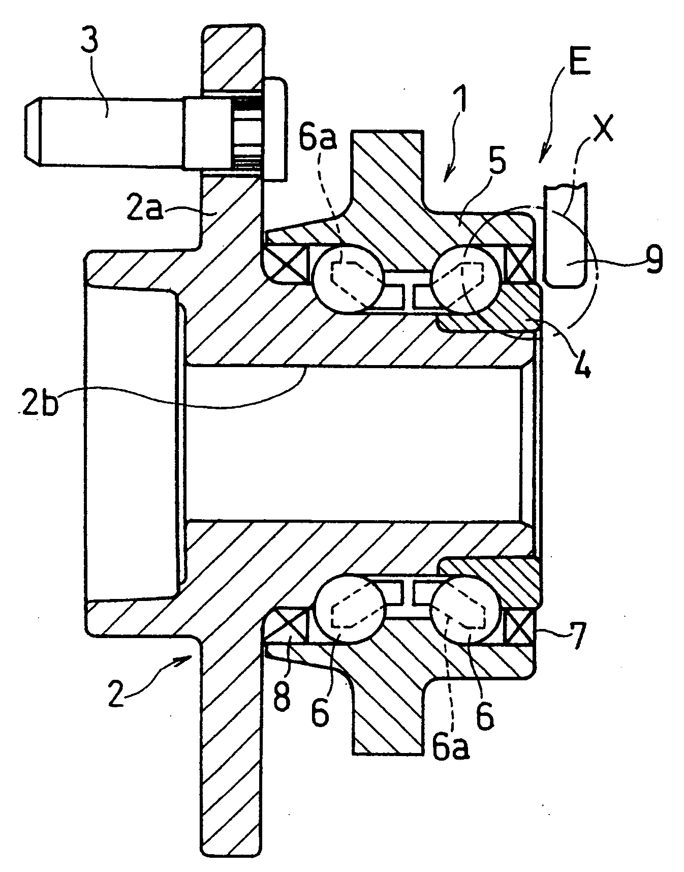
[0024]FIG. 1 shows one example of a supporting structure of the vehicle wheel with a rolling bearing unit 1. A tire wheel (not shown) is fixed to a hub flange 2a of a hub 2 constituting an inner wheel (rotary side member) with a bolt 3. The drive shaft (not shown) is spline fitted in a spline hole 2b formed in the hub 2 and the rotary drive force of the drive shaft is transmitted to the tire wheel. The hub 2 constitutes an inner wheel together with an inner wheel member 4. An outer wheel (fixed side member) 5 is fixed to the vehicle suspension (not shown). Two rows of rolling elements (ball) 6 . . . are interposed between the outer wheel 5 and the inner wheel (hub 2 and inner wheel member 4) while being held with a retainer 6a. Seal rings 7, 8 are pressed and fitted between the outer wheel 5 and the inner wheel (hub 2 and inner wheel member 4) in order to prevent leakage of lubricant (such as grease) filled in a rolling portion of the rolling elements 6 . . . or to prevent entering ...

embodiment 2

[0034]FIG. 6 shows other embodiment of a tone wheel of the present invention and the configuration of the metal reinforcing ring 13 of the tone wheel 10D is different from the above-mentioned embodiments. The metal reinforcing ring 13 comprises a cylindrical portion 13a to be fitted and fixed into the external peripheral face or inner peripheral face of the rotary side member, an inward brim portion 13d integrally formed at one end, and a small caliber cylindrical portion 13f concentrically extending from the direction opposite to the cylindrical portion 13a at the inner circumferential edge of the inward brim portion 13d. The inner diameter of the plastic magnet 14 is designed to be substantially the same as or a little larger than the external diameter of the small caliber cylindrical portion 13f of the metal reinforcing ring 13 and the fixation and integration of the metal reinforcing ring 13 and the plastic magnet 14 by means of adhesive 15 are done via a press-fit relation alon...

embodiment 3

[0037]FIG. 7 shows a still other embodiment 10E of a tone wheel of the present invention. The tone wheels 10, 10A-10D of the above-mentioned embodiments constitute an axial encoder, however the tone wheel 10E of this embodiment is different from them in that it constitutes a radial encoder. The metal reinforcing ring 13 comprises a cylindrical portion 13g to be fitted and fixed into the external peripheral face of the rotary side member, an outward brim portion 13h integrally formed at one end of the cylindrical portion 13g and a bent outward brim portion (bent portion) 13i formed at the other end of the cylindrical portion 13g thereafter. The plastic magnet 14 is a cylindrical body capable of externally fitting into the cylindrical portion 13g of the metal reinforcing ring 13. After it is externally fitted in the cylindrical portion 13g via the adhesive 15, the other end of the cylindrical portion 13g is bent outwardly to form the bent outward brim portion 13i, thereby forming the ...


PUM

PropertyMeasurementUnit
weight percentaaaaaaaaaa
circumferenceaaaaaaaaaa
rotationaaaaaaaaaa

Abstract

A tone wheel constituting a rotation detection magnetic encoder in combination with a magnetic sensor fixed onto a stationary side member, the tone wheel comprising a metal reinforcing ring fitted in a rotary side member and a circular multipolar magnet fixed to the metal reinforcing ring. the circular multipolar magnet is made of a plastic magnet of a circular resin molded product which contains a magnetic powder therein and is magnetized with a number of S and N poles alternatively along its circumference; the circular multipolar magnet is fixed to a surface of the metal reinforcing ring opposed to the magnetic sensor with an adhesive; and a restraint portion is provided at a part of the portion wherein the circular multipolar magnet is fixed to the metal reinforcing ring, thereby fixation of the circular multipolar magnet to the metal reinforcing ring is reinforced and depart of the circular multipolar magnet from the metal reinforcing ring is prevented.

Description

TECHNICAL FIELD[0001]The present invention relates to a tone wheel constituting a magnetic encoder for detecting the rotation number of the wheel of automobile and more particularly relates to a tone wheel provided so as to detect the rotation number of the wheel to be applied to an antilock brake system or a traction control system of automobiles.BACKGROUND ART[0002]The wheel of automobile is sometimes equipped with a magnetic encoder for detecting the rotation number. Such a magnetic encoder may be comprised of a tone wheel constituted with a rotating member of the wheel like a slinger (metal reinforcing ring) of a seal ring of a wheel bearing system and a magnetic sensor which is fixed on the automobile body (stationary member side) and is provided so as to closely confront the surface of the tone wheel. On the other hand, a tone wheel may be employed such that it is fitted in and fixed to the rotary side member via a metal reinforcing ring other than the seal ring and confronts ...

Claims


Application Information

Patent Timeline
Patent Type & Authority Applications(United States)
IPC IPC(8): H01F7/02
CPCG01D5/145G01P3/443F16C19/186F16C41/007G01P3/487
Inventor MIZUTA, HIDEO
Owner UCHIYAMA MFG
Why Eureka
Try Eureka