
High voltage transformer with a shield ring. a shield ring and a method of manufacture same

a high-voltage transformer and shield ring technology, applied in transformers/inductances, magnets, magnetic cores of magnets, etc., can solve the problems of high-voltage windings that cannot be insulated, and achieve high mechanical force, reduce electrical stress in transformer oil, and high mechanical strength and thermal properties

Active Publication Date: 2010-01-14
HITACHI ENERGY SWITZERLAND AG
View PDF1 Cites 24 Cited by
  • Summary
  • Abstract
  • Description
  • Claims
  • Application Information

AI Technical Summary

Benefits of technology

The present invention provides a high voltage transformer with a shield ring that has reduced electrical stress in critical areas outside the shield ring, while still maintaining high mechanical strength and thermal properties in part of the shield ring subjected to high mechanical forces as well as high demands on thermal properties. The shield ring is designed to have superior properties compared to prior art shield rings. The invention also provides a method of manufacturing the shield ring. The amount of solid insulation on the corners of the shield ring is relatively high in the invention, which reduces the electric stress in oil outside the shield ring solid insulation layer by taking a higher degree of voltage drop in the solid insulation itself. The amount of solid insulation in the vertical direction is limited to transfer the spring force of the winding efficiently towards the yoke. The invention allows for the adaptation of the amount of solid insulation in every direction to meet specific needs.

Problems solved by technology

A main insulation problem at a core-type transformer is the problem of insulating high voltage windings from the core and from neighboring windings.

Method used


Image

  • High voltage transformer with a shield ring. a shield ring and a method of manufacture same
  • High voltage transformer with a shield ring. a shield ring and a method of manufacture same
  • High voltage transformer with a shield ring. a shield ring and a method of manufacture same

Examples


Embodiment Construction

[0024]In the following a detailed description of a preferred embodiment of the present invention will be given.

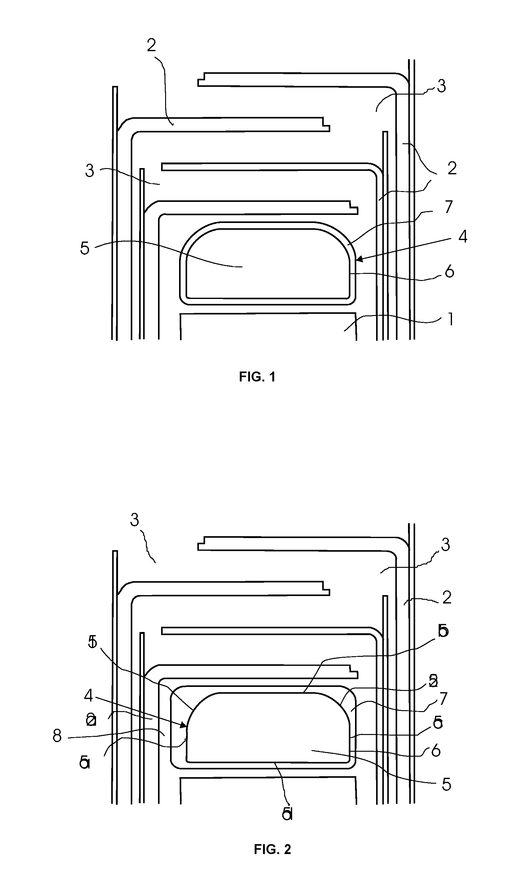
[0025]A prior art shield ring and surrounding insulation structure has been described in the background section with reference to FIG. 1 and this figure will not be further discussed herein.

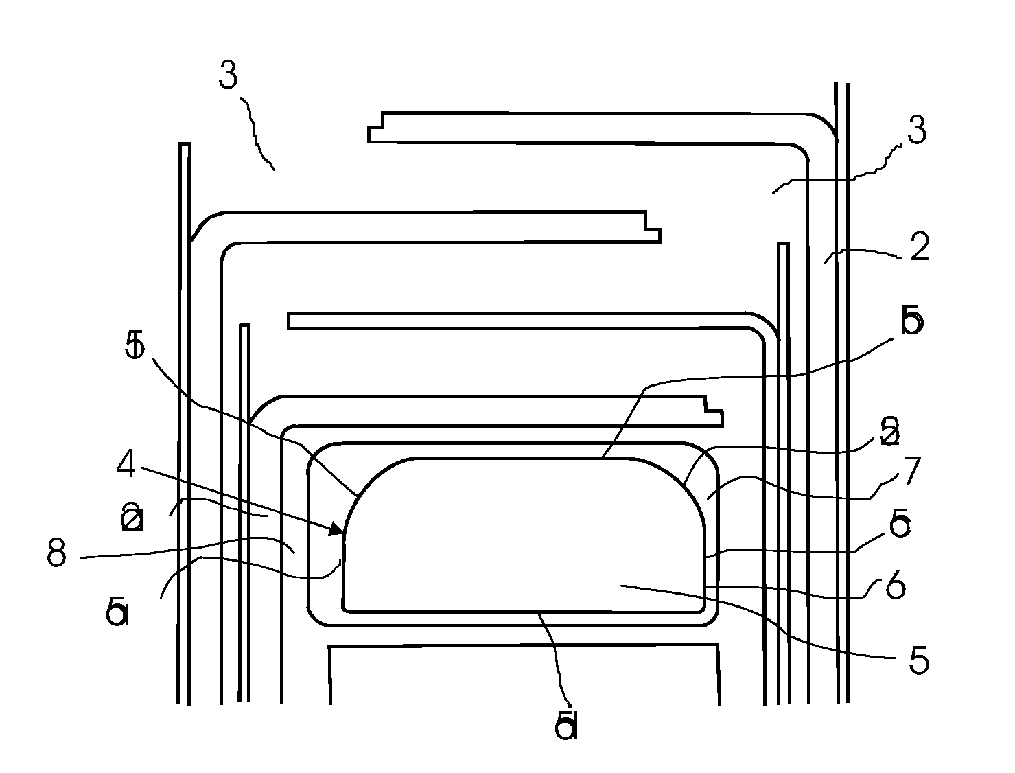
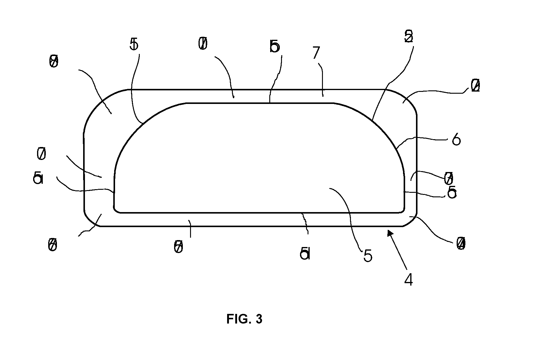
[0026]In FIG. 2, there is shown a view of a shield ring 4 and surrounding insulation structure according to the invention and FIG. 3 is a schematic cross section view illustrating a shield ring according to the invention in detail.

[0027]In FIG. 2, 1 is the winding end 1 of high voltage winding in a power transformer, which is shielded by an insulation structure consisting of pressboard barriers 2 which form a zigzag pattern in surrounding transformer oil 3. 4 is a shield ring used to increase the insulation on the corners of the winding end 1 more than is possible by adapting the insulation of current-carrying conductor of the winding itself. The shield ring 4 is built up from a core 5, ...


PUM

PropertyMeasurementUnit
heightaaaaaaaaaa
heightaaaaaaaaaa
DC voltagesaaaaaaaaaa

Abstract

A high voltage transformer including a transformer housing. Internal components and provided in the transformer housing. The internal components are submerged in transformer oil and are provided with insulation for insulating a high voltage winding end. The insulation includes a shield ring arranged above the winding end and a pressboard structure formed in a zigzag pattern arranged around the winding end. The shield ring includes a core covered with a conducting layer and a continuous solid insulation layer outside the conducting layer. The insulation layer includes integrated solid insulation sections of which at least some among themselves having varying thickness. Also a shield ring and a method of manufacture the shield ring.

Description

FIELD OF INVENTION[0001]The present invention relates to a high voltage transformer comprising transformer housing; internal components, such as transformer core, yokes and windings, provided in the transformer housing, the internal components being submerged in transformer oil, wherein the internal components are provided with insulation structure comprising means for insulation the high voltage winding end, which insulation means comprises a shield ring arranged above the winding end and a pressboard structure formed in a zigzag pattern arranged around the winding end and said shield ring, which shield ring comprises a core, covered with a conducting layer, potentially connected to the winding end and a continuous solid insulation layer outside the conducting layer.[0002]The invention also relates to a shield ring for use in power transformers and reactors and submersed in transformer oil, comprising a core covered by a conducting outer layer and a continuous outer solid insulatio...

Claims


Application Information

Patent Timeline
Patent Type & Authority Applications(United States)
IPC IPC(8): H01F27/36H01F41/00
CPCH01F27/2885Y10T29/49073H01F27/362H01F27/36H01F27/363
Inventor FORSBERG, ERIKPOLANDER, TONYSVENSSON, LARS- KEVENNERBERG, LARS-ERIK
Owner HITACHI ENERGY SWITZERLAND AG
Learn More