Display unit having a dial and a central display

a display unit and dial technology, applied in the field of display units, can solve the problems of difficult to eliminate the irregular luminescence of the indicating needle, and the conventional display unit b>1/b> has another problem, so as to prevent thermal deformation of the substrate, increase the brightness of the illumination of the needle portion 644, and facilitate the attachment to the substrate

Inactive Publication Date: 2010-01-14
YAZAKI CORP
View PDF2 Cites 13 Cited by
  • Summary
  • Abstract
  • Description
  • Claims
  • Application Information

AI Technical Summary

Benefits of technology

[0021]In one implementation, a film may be provided on side surfaces of the substrate for prevention of thermal deformation of the substrate.
[0022]Preferably, the light guide includes (a) a first reflecting surface provided at a connecting portion between the first light-guide portion and the second light-guide portion such that a light emitted by the light source and traveling inside of the first light-guide portion is reflected off the first reflecting surface and the reflected light further travels inside of the second light-guide portion, (b) a second reflecting surface provided at a connecting portion between the second light-guide portion and the third light-guide portion such that the light traveling inside of the second light-guide portion is reflected off the second reflecting surface and the reflected light further travels inside of the third light-guide portion, and (c) a third reflecting surface provided at a connecting portion between the third light-guide portion and the needle portion such that the light traveling inside of the third light-guide portion is reflected off the third reflecting surface and the reflected light further travels inside of the needle portion toward the other end of the needle portion.
[0023]With the construction and arrangement described above, the number of times of reflection during turning of the indicating needle 6 can be reduced from conventional five (5) to three (3), and thus the brightness of illumination of the needle portion 644 can be increased.
[0024]Preferably, the light guide may include in one piece therewith a fixing member including a pair of nails each provided on an underside of the first light-guide portion in the axial direction so as to sandwich the both edges of the substrate in the width direction, and a slide grooves into which the both edges of the substrate are slidably inserted, the slide grooves being formed on inner surfaces of the pair of nails. It is appreciated that the light guide can be readily attached to the substrate by just inserting the both edges of the substrate in the slide grooves and sliding the light guide.
[0025]Preferably, the display unit may include a light-guide cover. The light cover is configured to cover the outer surfaces of the light guide except for a top surface of the needle portion so as to prevent leakage of light. Since the light-guide cover prevents a light from exiting surfaces other than the top surface of the needle portion, the light-guide cover contributes to improved quality of appearance of the indicating needle.
[0026]Preferably, the light-guide cover includes a white body made of a white material and a black coating provided on the outer surface of the white body. An advantage of the light-guide cover having the white body is that the light that may leak out of the light-guide cover is reflected off the white body and the reflected light is again guided through the light guide 64 to the needle portion 644, and thus the brightness of luminescence of the needle portion is further improved. Also, by virtue of the white body of the cover, brightness of luminescence on the top surface of the needle portion can be further improved. At the same time, by virtue of the black outer surface, the light that may pass the white body of the light-guide cover to an outside is absorbed by the black surface, and thus the leakage of light is effectively prevented.

Problems solved by technology

A drawback of the conventional display unit 1 is that it is necessary to arrange the plurality of LED light sources 10 around the shaft 52 in order to make the indicating needle 6 emit light, making it difficult to eliminate the irregular luminescence of the indicating needle 6 due to turning of the indicating needle.
Apart from the problem of the needle's irregular luminescence, the conventional display unit 1 has another problem.

Method used


Image

  • Display unit having a dial and a central display
  • Display unit having a dial and a central display
  • Display unit having a dial and a central display

Examples


Embodiment Construction

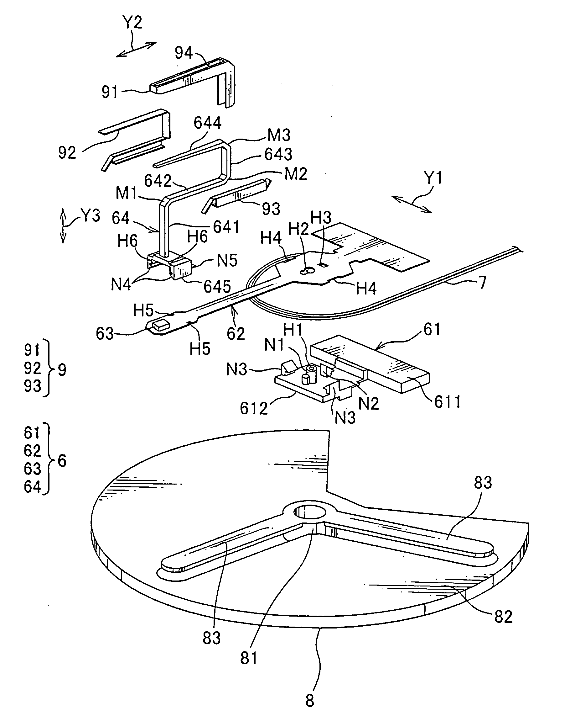
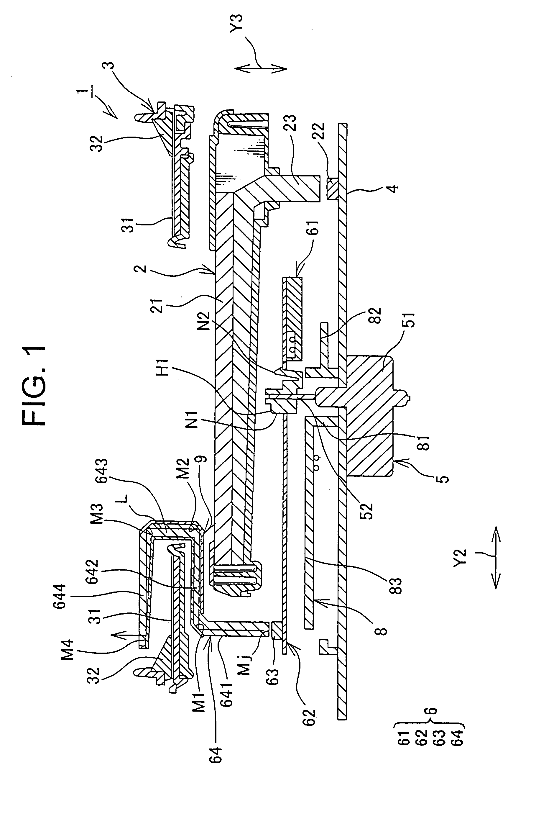
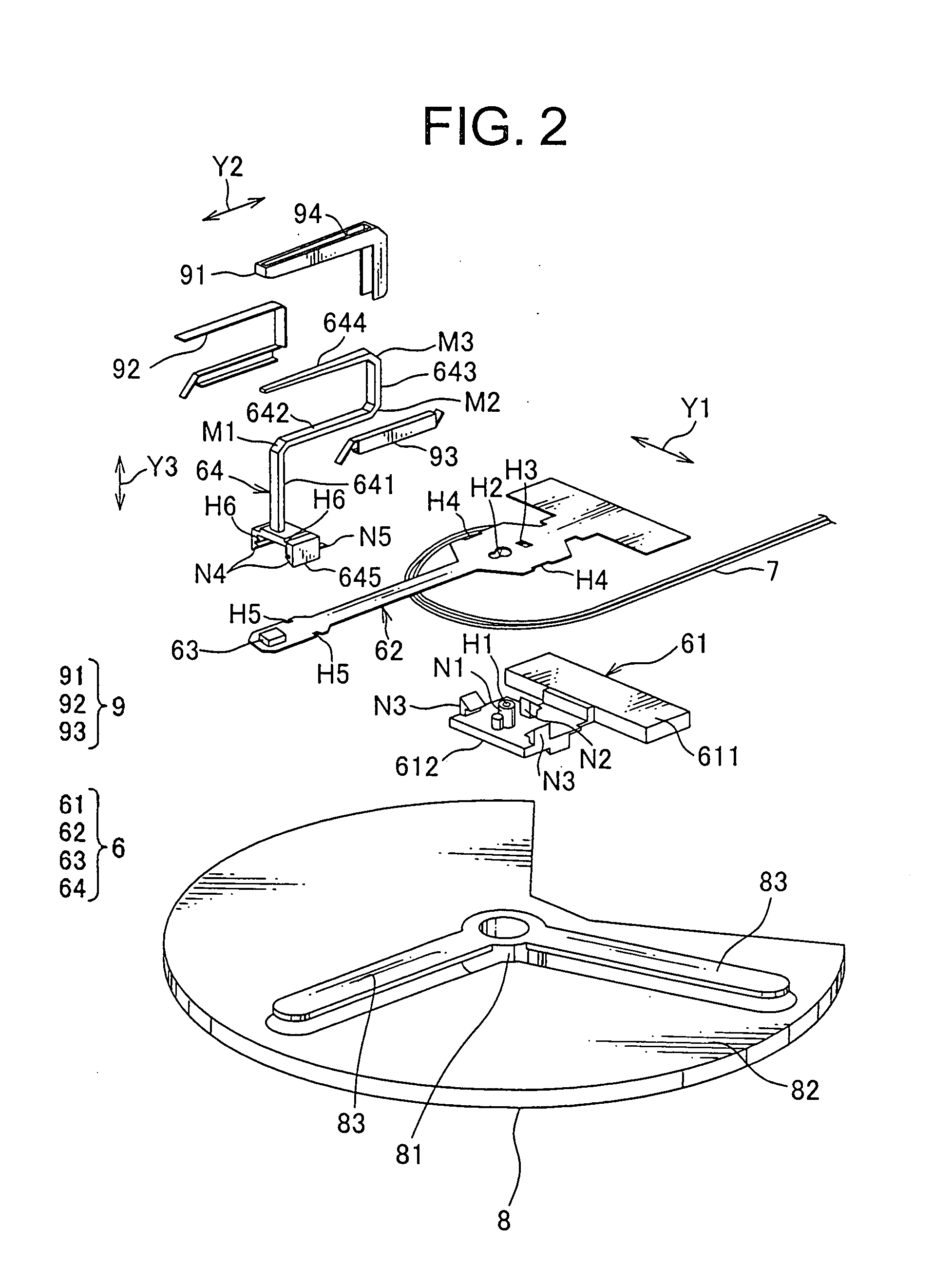
[0035]With reference to FIGS. 1 to 3, and in particular with reference to FIG. 1, there is shown a display unit 1 in accordance with a preferred embodiment of the present invention. The display unit 1 includes an display device, which is, but not limited to, a liquid crystal display (LCD) device 2, a dial assembly 3, a main board 4, a motor 5, an indicating needle 6, a lead wire 7, and a regulation portion 8.

[0036]Referring to FIG. 1, the LCD device 2 may be formed in a substantially circular shape and is used to indicate information such as warning and current time. The LCD device 2 includes a body 21, an LED light source 22 for backlighting, which is provided on the main board 4, and a light-guiding plate 23 that guides light beams emitted by the LED light source 22 to an underside of the body 21 of the LCD device 2.

[0037]As shown in FIG. 1, the dial assembly 3 has a dial 31 and a ring-shaped scale portion 32. The dial 31 is formed in a shape of a ring or a doughnut (which may be ...


PUM


Abstract

Provided is a display unit that incorporates a dial, a central display device, and an indicating needle. The indicating needle includes a substrate provided beneath the display device, a light source on a surface of an end of the substrate; and a light guide. The light guide includes a first light-guide portion extending vertically with its lower end facing the light source of the substrate, a second light-guide portion extending horizontally from the first light-guide portion, a third light-guide portion extending vertically from the second light-guide portion, and a needle portion extending horizontally such that the dial is pointed to by the end of the needle portion. The display unit may include a light-guide cover that prevents leakage of light and a regulation portion that restricts undesirable movement of a lead wire which might obstruct with rotation of the indicating needle.

Description

CROSS-REFERENCE TO RELATED APPLICATION[0001]The priority application Japan Patent Application No. 2008-178769 upon which this patent application is based is hereby incorporated by reference.BACKGROUND OF THE INVENTION[0002]1. Field of the Invention[0003]The present invention relates generally to a display unit for an automobile or other vehicle, and more particularly to a display unit incorporating a dial of a revolution indicator such as a tachometer and a speedometer and a display device such as an LCD unit arranged at the center of the dial.[0004]2. Description of the Related Art[0005]A dial of a revolution indicator and a display device arranged on the surface of the dial are commonly used in a known display unit of an automobile or other vehicle. Such design is most often intended to ensure good visibility of the display device regardless of the presence of an indicating needle that points to a scale of the dial and while allowing the display device to be arranged at the center...

Claims


Application Information

Patent Timeline
Patent Type & Authority Applications(United States)
IPC IPC(8): G08B5/24B60Q1/00
CPCB60K37/02B60K2350/203G01D13/265G01D11/28G01D7/002B60K2370/33B60K2370/698B60K2370/336B60K2370/6992B60K2370/6985B60K35/00G01D13/04G01D13/22
Inventor ONO, HARUYOSHI
Owner YAZAKI CORP
Why Eureka
Try Eureka