Dual-polarized phased array antenna with vertical features to eliminate scan blindness

a phased array antenna and vertical feature technology, applied in the field of communication, can solve the problems of significant deformation of array gain, scan blindness for certain scan angles, and current state of the art that does not permit wide-angle scanning applications of csa, and achieve the effect of reducing the gain of the broadside (non-scanned) array and avoiding scan blindness

Inactive Publication Date: 2010-01-14
HARRIS CORP
View PDF10 Cites 46 Cited by
  • Summary
  • Abstract
  • Description
  • Claims
  • Application Information

AI Technical Summary

Benefits of technology

[0006]A phased array antenna includes a substrate and an array of antenna unit cells formed on the substrate. Each antenna unit cell comprises first and second sets of coupled dipole antenna elements that are orthogonal to each other and provide dual polarization. A v

Problems solved by technology

In many cases, the phased array lattice is constrained to a size which is larger than optimum due to manufacturing limitations and usage of existing RF modules.
Severe impedance mismatch causes scan blindness for certain scan angles if the array lattice is greater than one-half (½) wavelength.
The array gain is significantly degraded

Method used


Image

  • Dual-polarized phased array antenna with vertical features to eliminate scan blindness
  • Dual-polarized phased array antenna with vertical features to eliminate scan blindness
  • Dual-polarized phased array antenna with vertical features to eliminate scan blindness

Examples


Embodiment Construction

[0019]Different embodiments will now be described more fully hereinafter with reference to the accompanying drawings, in which preferred embodiments are shown. Many different forms can be set forth and described embodiments should not be construed as limited to the embodiments set forth herein. Rather, these embodiments are provided so that this disclosure will be thorough and complete, and will fully convey the scope to those skilled in the art. Like numbers refer to like elements throughout.

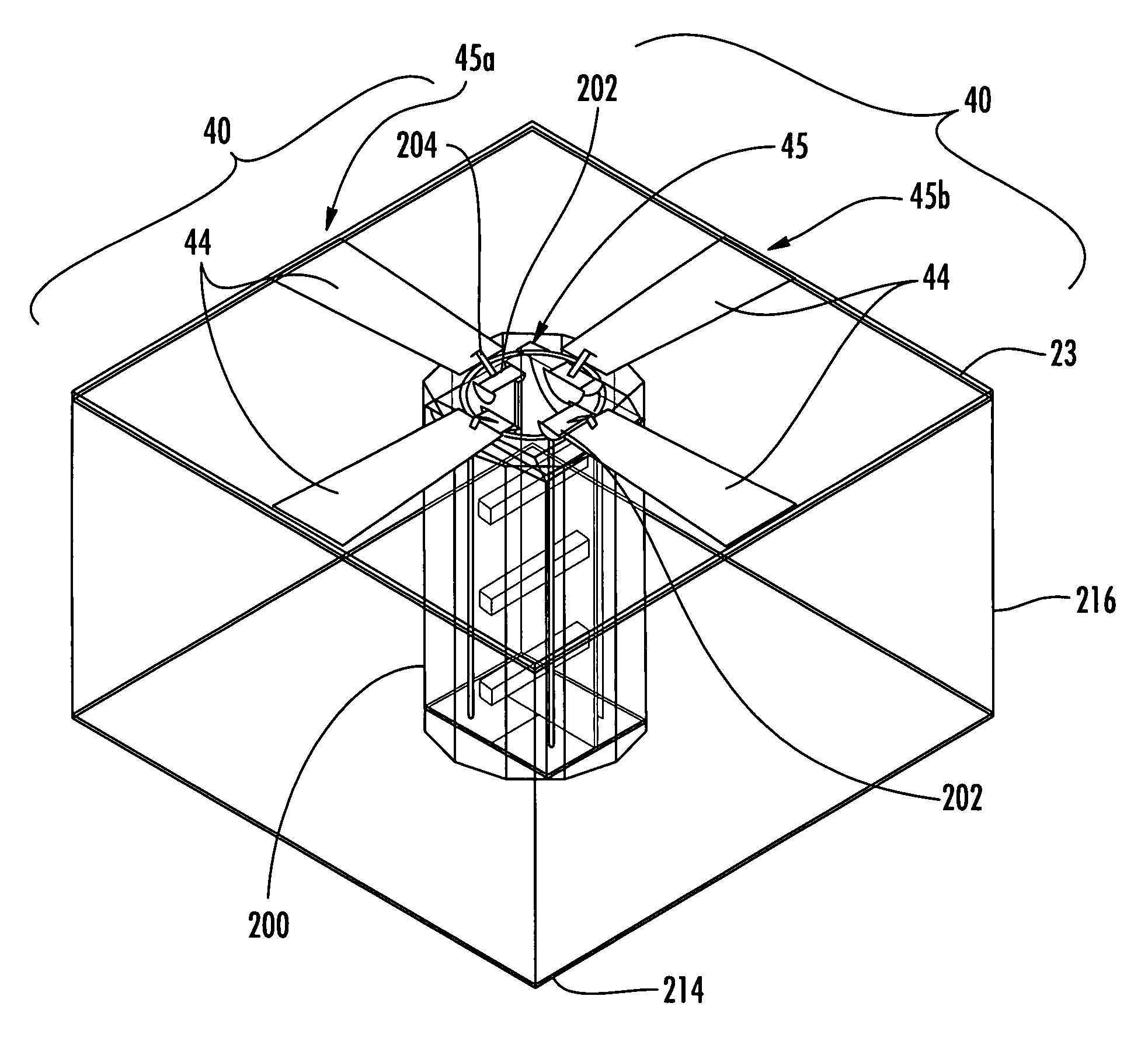
[0020]In accordance with a non-limiting example of the present invention, scan blindness can be eliminated in the larger array lattices used for dual-polarized current sheet arrays. It has been determined that scan blindness is interdependent upon the array lattice, element feed implementation, and dielectric layers Narrow vertical members, such as formed as metallic ribs or pins, can be positioned between the coupled elements in both polarizations to eliminate scan blindness without degrading ...


PUM

PropertyMeasurementUnit
Metallic bondaaaaaaaaaa

Abstract

A phased array antenna includes a substrate and an array of antenna unit cells formed on the substrate. Each antenna unit cell comprises first and second sets of coupled dipole antenna elements that are orthogonal to each other and provide dual polarization. A member is positioned at each antenna unit cell between each of the dipole antenna elements in each polarization to eliminate scan blindness without reducing broadside (non-scanned) array gain.

Description

FIELD OF THE INVENTION[0001]The present invention relates to the field of communications, and more particularly, the present invention relates to phased array antennas.BACKGROUND OF THE INVENTION[0002]Lightweight phased array antennas having a wide frequency bandwidth and a wide scan angle can be economically manufactured and conformally mounted on a surface, such as a nose cone of an aircraft. Examples of such antenna include a current sheet array (CSA) formed of capacitively-coupled dipole elements embedded in dielectric layers above a ground plane. The capacitors often are formed as interdigitated “fingers.” The coupling capacitance between dipole elements can be increased by lengthening the capacitor “digits” or “fingers,” which results in additional bandwidth for the antenna. An example of this type of structure is disclosed in commonly assigned U.S. Pat. No. 6,512,487 to Durham, the disclosure which is hereby incorporated by reference in its entirety.[0003]Often this type of p...

Claims


Application Information

Patent Timeline
IPC IPC(8): H01Q21/26H01Q9/28H01P11/00
CPCH01Q9/28Y10T29/49016H01Q21/26H01Q21/24
Inventor JONES, ANTHONY M.TRENT, CHRISTOPHER
Owner HARRIS CORP
Why Eureka
Try Eureka