Optical waveguide for touch panel and touch panel using the same

a technology of optical transmission and touch panel, which is applied in the direction of optical waveguide light guide, instruments, computing, etc., can solve the problems of low optical transmission efficiency, inability to accurately detect, and the position of the portion of the display screen touched with the finger cannot be accurately detected, so as to enhance optical transmission efficiency, improve productivity, and improve productivity

Inactive Publication Date: 2010-01-14
NITTO DENKO CORP
View PDF5 Cites 17 Cited by
  • Summary
  • Abstract
  • Description
  • Claims
  • Application Information

AI Technical Summary

Benefits of technology

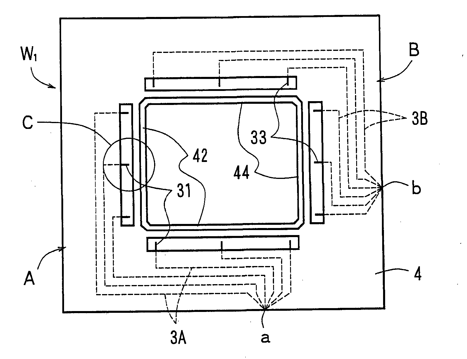
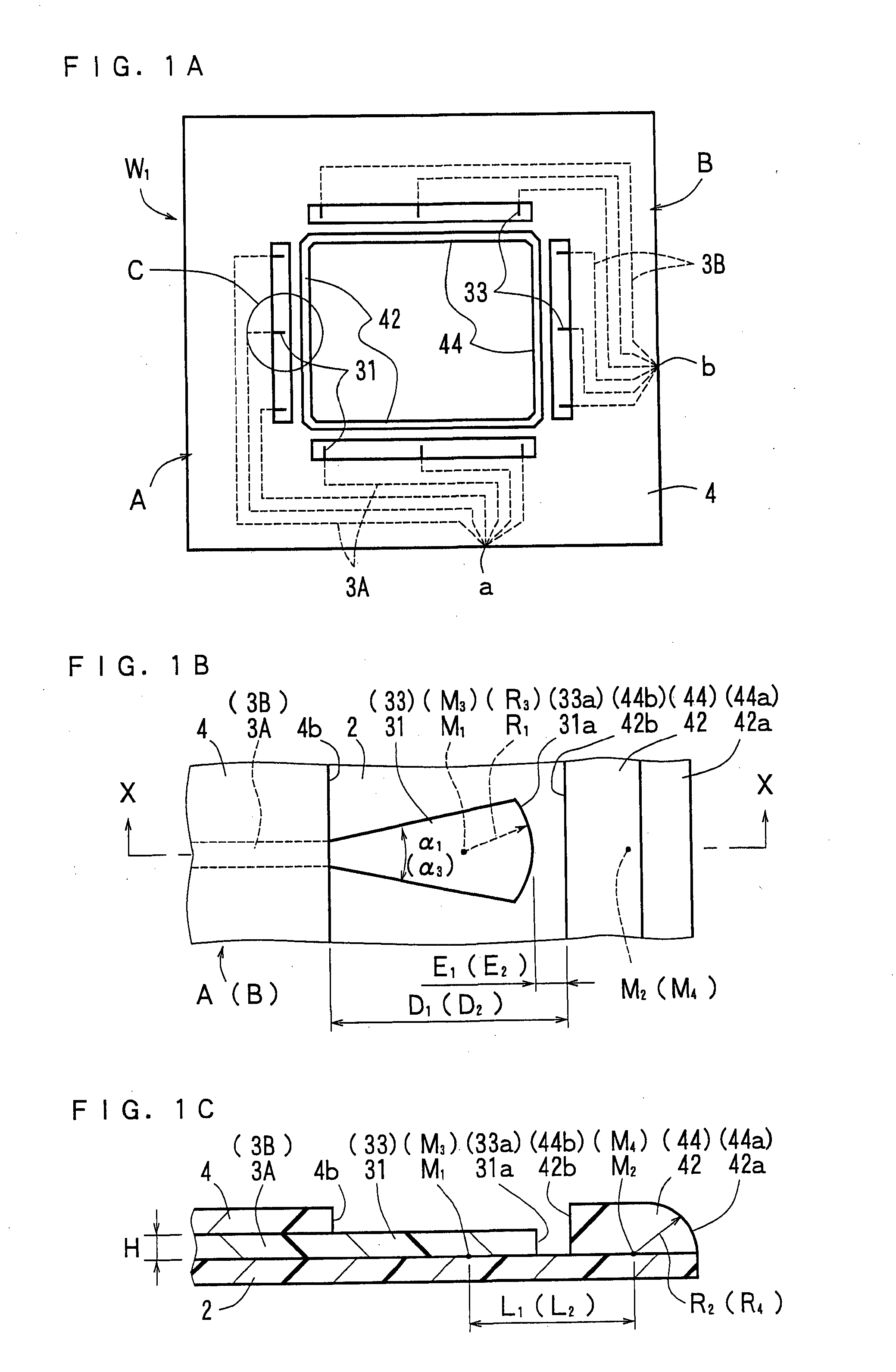
[0013]To solve the above-mentioned problem, the present inventor has discovered the idea of forming the core end portion as the first lens portion and thereafter forming the second lens portion as the extension of the over cladding layer in front of the above-mentioned first lens portion when the over cladding layer is formed. Since the cores and the over cladding layer are originally integral, this allows the optical waveguide for the touch panel according to the present invention to achieve alignment between the first lens portion provided in the core end portion and the second lens portion as the extension of the over cladding layer when the over cladding layer is formed.
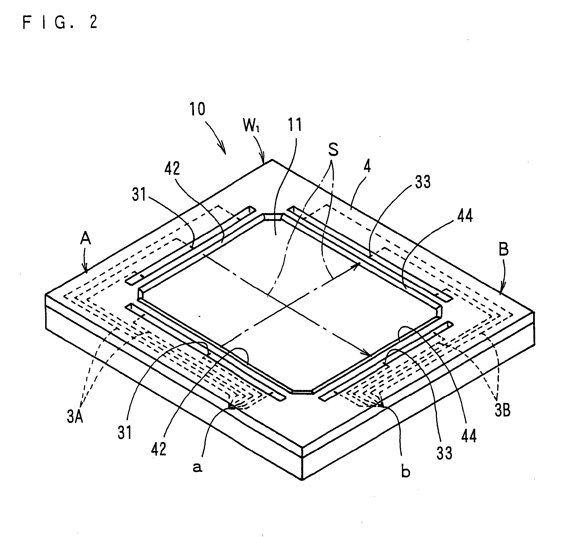
[0014]In the optical waveguide for the touch panel according to the present invention, the end portion of the light-emitting core is formed as the first lens portion having the lens surface of an arcuate shape as seen in plan view which bulges outwardly, and the second lens portion having a lens surface of an arcuate shape as seen in sectional side view which bulges outwardly is formed as the extension of the over cladding layer, the second lens portion being spaced apart from the lens surface of the first lens portion. Thus, the optical waveguide for the touch panel according to the present invention is capable of achieving automatic alignment between the first lens portion provided in the core end portion and the second lens portion including the extension of the over cladding layer when the over cladding layer is formed. This eliminates the need for the process of aligning the above-mentioned first lens portion and the second lens portion with each other to improve productivity.
[0015]Further, when the above-mentioned first lens portion has a width increasing gradually toward an end surface thereof closer to the above-mentioned second lens portion to have a substantially sectorial shape, and an arcuate surface portion of the substantially sectorial shape is formed as the above-mentioned first lens surface, then the light beams coming from the basal portion of the above-mentioned first lens portion into the widened portion thereof diverge substantially uniformly along the shape of the widened portion, and the light beams reach the lens surface at the end surface substantially uniformly. This allows the emission of wide light beams from the lens surface of the above-mentioned first lens portion, with the intensity of the light beams maintained substantially uniformly across the width thereof. As a result, if the position of a finger having touched the display screen of the display in the touch panel is slightly deviated from a predetermined position, the position of the portion touched with the finger is appropriately detected because of the above-mentioned wide light beams.
[0016]Further, when the cores include a light-receiving core for receiving the above-mentioned emitted light beams and having an end portion positioned in a second side portion of the display screen of the above-mentioned display, the end portion of the above-mentioned light-receiving core is formed as a third lens portion in such a manner as to protrude from another edge portion of the above-mentioned over cladding layer and to be exposed to the outside air, the above-mentioned third lens portion has a third lens surface of an arcuate shape as seen in plan view which bulges outwardly, the over cladding layer further includes a fourth lens portion formed as another extension of the above-mentioned over cladding layer and corresponding to the above-mentioned third lens portion, the above-mentioned fourth lens portion being spaced apart from the third lens surface of the above-mentioned third lens portion, and the above-mentioned fourth lens portion has a fourth lens surface of an arcuate shape as seen in sectional side view which bulges outwardly, then automatic alignment is achieved between the third lens portion and the fourth lens portion when the over cladding layer is formed in a manner similar to that between the above-mentioned first and second lens portions on the light-emitting side. This improves productivity.
[0017]Also, when the above-mentioned third lens portion has a width increasing gradually toward an end surface thereof closer to the fourth lens portion to have a substantially sectorial shape, and an arcuate surface portion of the substantially sectorial shape is formed as the above-mentioned third lens surface, then it is easy for light beams to enter the lens surface of the third lens portion because the lens surface of the above-mentioned third lens portion is wide. This enhances optical transmission efficiency to achieve more accurate detection of the position of a finger having touched the display screen of the display in the touch panel.
[0018]The touch panel according to the present invention includes the above-mentioned optical waveguide for the touch panel. Thus, the light beams emitted from the end surface of the core are restrained from diverging. This achieves the accurate detection of the position of a finger having touched the display screen of the display.

Problems solved by technology

In this state, optical transmission efficiency is low, and it is impossible to accurately detect the above-mentioned position of the portion touched with the finger.
Unless the alignment is performed accurately, the divergence of the light beams S is not appropriately restrained on the light-emitting side, and, consequently, the position of the portion of the display screen of the display touched with the finger cannot be detected accurately.
However, the accurate alignment requires precision and is hence difficult.
It is labor- and time-consuming to achieve the accurate alignment.

Method used


Image

  • Optical waveguide for touch panel and touch panel using the same
  • Optical waveguide for touch panel and touch panel using the same
  • Optical waveguide for touch panel and touch panel using the same

Examples


examples

Material for Formation of Under Cladding Layer and Over Cladding Layer

[0062]A material for formation of an under cladding layer and an over cladding layer was prepared by mixing 100 parts by weight of an epoxy resin having an alicyclic skeleton (EP4080E manufactured by ADEKA Corporation) (component A), and 2 parts by weight of a photo-acid generator (CPI-200K manufactured by SAN-APRO Ltd.) (component B) together.

Material for Formation of Cores

[0063]A material for formation of cores was prepared by dissolving 40 parts by weight of an epoxy resin having a fluorene skeleton (OGSOL EG manufactured by Osaka Gas Chemicals Co., Ltd.) (component C), 30 parts by weight of a polyfunctional fluorene epoxy (EX-1040 manufactured by Nagase ChemteX Corporation) (component D), 30 parts by weight of 1,3,3-tris{4-[2-(3-oxetanyl)]butoxyphenyl}butane (component E), and one part by weight of the aforementioned component B in 40.8 parts by weight of ethyl lactate.

Production of Optical Waveguide for Touch...


PUM


Abstract

An optical waveguide for a touch panel which eliminates the need for alignment between the optical waveguide and a lens device, and a touch panel using the same. An end portion of a light-emitting core for emitting light beams and an end portion of a light-receiving core for receiving emitted light beams are formed as first and third lens portions so as to protrude from edge portions of an over cladding layer and to be exposed to outside air. The first and third lens portions have lens surfaces which bulge outwardly. The over cladding layer includes second and fourth lens portions formed as extensions of the over cladding layer and corresponding to the first and third lens portions, with the second and fourth lens portions spaced apart from the lens surfaces of the first and third lens portions. The second and fourth lens portions have lens surfaces which bulge outwardly.

Description

RELATED APPLICATIONS[0001]This application claims the benefit of U.S. Provisional Application No. 61 / 082,987, filed Jul. 23, 2008, which is hereby incorporated by reference.BACKGROUND OF THE INVENTION[0002]1. Field of the Invention[0003]The present invention relates to an optical waveguide for a touch panel and a touch panel using the same.[0004]2. Description of the Related Art[0005]A touch panel is an input device for operating an apparatus by directly touching a display screen of a liquid crystal display device or the like with a finger, a purpose-built stylus or the like. The touch panel includes a display which displays operation details and the like, and a detection means which detects the position (coordinates) of a portion of the display screen of the display touched with the finger or the like. Information indicating the touch position detected by the detection means is sent in the form of a signal to the apparatus, which in turn performs an operation and the like displayed...

Claims


Application Information

Patent Timeline
Patent Type & Authority Applications(United States)
IPC IPC(8): G06F3/042G02B6/32
CPCG02B6/138G02B6/32G06F3/0421G02B2006/12102G02B2006/12073G06F3/0412
Inventor JUNI, NORIYUKI
Owner NITTO DENKO CORP
Why Eureka
Try Eureka