
Channel estimation of multi-carrier signal with selection of time or frequency domain interpolation according to frequency offest of continuous pilot

Active Publication Date: 2010-01-14
III HLDG 6
View PDF7 Cites 22 Cited by
  • Summary
  • Abstract
  • Description
  • Claims
  • Application Information

AI Technical Summary

Benefits of technology

[0006]Therefore, it is an object of the invention to provide a straightforward and economical way of performing equalization in an OFDM receiver.
[0009]The ‘time-domain’ interpolation can be followed by an additional frequency-domain interpolation, and, since relatively stationary conditions are required for successful equalization using this technique, this type of equalizer may simply be referred to as a ‘static equalizer’. Static equalization is based on an assumption that the channel characteristics will not change significantly from one multi-carrier symbol to the next, and can use this property to provide an accurate channel estimation.
[0011]An obvious advantage of the method according to the invention is that a frequency offset or Doppler shift in the received signal can easily and quickly be identified on the basis of the continual pilots whose positions in each OFDM symbol are known, since the frequency-domain interpolator does not make any assumption as to the stability of the channel. Therefore, the switchover from the time-domain interpolator to the frequency-domain interpolator can take place in good time, before failure of the time-domain interpolator, allowing data to be recovered from the multi-carrier signal also in a mobile environment. Since the continual pilots of the received signal are continually examined for any frequency offset, it can easily be determined if the transmitter and receiver are once more essentially stationary with respect to each other, so that a switchover back to the—preferred—time-domain interpolation can also be carried out in an easy and straightforward manner. Furthermore, since the frequency-domain interpolator uses the continual pilots of an OFDM symbol, whose positions in the symbol are known, this interpolator can estimate the channel using only a single OFDM symbol. The decision to switch over, therefore, can be made more rapidly than is possible in other state of the art systems. In this way, the best channel estimation method to estimate the transmission channel of a multi-carrier signal in a mobile environment can be easily and rapidly chosen.
[0020]The time-domain and frequency-domain interpolators of the system according to the invention can perform complete channel estimation, i.e. each of the interpolators can identify each of the carriers of the incoming multi-carrier symbol to obtain the channel transfer function required for recovery of the original transmitted data. However, a time-domain interpolator requires a certain number of entire OFDM symbols to interpolate all of the carriers, since time-domain interpolation uses the scattered pilots, and a ‘full set’ of scattered pilots is distributed over a number of OFDM symbols. This is one of the reasons why complete channel estimation by time-domain interpolation is costly. Therefore, in an alternative embodiment according to the invention, the system can comprise a rudimentary time-domain interpolator and a rudimentary frequency-domain interpolator, operating in parallel as described above, to perform partial channel estimation. For instance, these interpolators may identify one quarter of the carriers. A supplementary frequency-domain interpolator downstream of the selection unit can perform an additional channel estimation on the selected interpolator output to complete the interpolation. Such a system allows a more economical realisation, since it suffices to perform only a partial channel estimation in either the time-domain or frequency-domain, and further channel estimation is subsequently carried out in the supplementary frequency-domain interpolator.

Problems solved by technology

However, at higher speeds, for example when a user of a hand-held device (such as a mobile phone or pocket personal computer) is receiving a television broadcast while in a car or train, the received signal will be further distorted to a greater or lesser extent owing to the Doppler effect—i.e. the wavelengths of the carriers will be ‘compressed’ or ‘stretched’, depending on the direction and speed of travel of the user with respect to the transmitter.
The resulting perceived shift in the carrier frequencies results in a corruption of their orthogonality, which is increased even further by the time-interpolation, resulting in failures in the channel estimation process.
As a result, the user's device may fail to regain the originally transmitted data from the received signal.
However, state of the art solutions that are based on a switchover between time-domain and frequency-domain equalization are not fast enough in reacting to a rapid increase in velocity between the transmitter and receiver, since they require a large number of consecutive symbols in order to arrive at the decision to make the switch-over.
Furthermore, these state of the art solutions are generally quite complex at the receiver end.

Method used


Image

  • Channel estimation of multi-carrier signal with selection of time or frequency domain interpolation according to frequency offest of continuous pilot
  • Channel estimation of multi-carrier signal with selection of time or frequency domain interpolation according to frequency offest of continuous pilot
  • Channel estimation of multi-carrier signal with selection of time or frequency domain interpolation according to frequency offest of continuous pilot

Examples


Embodiment Construction

[0034]In the diagrams, like numbers refer to like objects throughout.

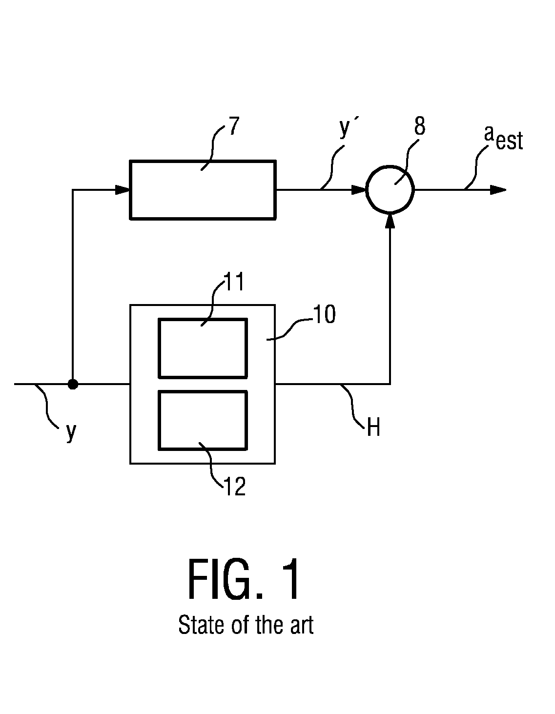
[0035]FIG. 1 shows a very simplified block diagram of an equalizer according to the state of the art. Only the blocks relevant to the following discussion are shown, and it will be understood that equalization involves a much greater number of stages than shown here, such as blocks for performing discrete fast-Fourier transformations, forward error correction, etc., as will be known to a person skilled in the art. A received multi-carrier signal y is input to an equalizer 10, where a first interpolator 11 performs static equalization, and a second interpolator 12 performs frequency-domain interpolation. The system can switch between the two equalizers, for example using one of the techniques of the prior art documents mentioned in the introduction. At the same time, the input signal y is delayed in a delay block 7 to compensate for the fact that the time-domain interpolation requires a certain length of time, for i...


PUM


Abstract

The invention relates to a method of estimating the transmission channel of a received multi-carrier signal (y) in a mobile environment, which method comprises identifying pilots (P1, P2, . . . , Pk) present on carriers of the received multi-carrier signal (y), which pilots (P1, P2, . . . , Pk) comprise continual pilots (P1, P2, . . . , Pk), performing channel estimation on the received multi-carrier signal (y) using a time-domain interpolator (3, 3′) to give a first interpolator output (30), and performing channel estimation on the received multi-carrier signal (y) using a frequency-domain interpolator (4, 4′) to give a second interpolator output (40). A frequency offset in a continual pilot (P1, P2, . . . , Pk) is detected, and either the first interpolator output (30) or the second interpolator output (40) is selected on the basis of the detected frequency offset. The invention also relates to a system (1) for estimating the transmission channel of a received multi-carrier signal (y) in a mobile environment, which system comprises an identification unit (2) for identifying pilots (P1, P2, . . . , Pk) present on carriers of the received multi-carrier signal (y) which pilots (P1, P2, . . . , Pk) comprise continual pilots (P1, P2, . . . , Pk), a time-domain interpolator (3, 3′) for performing channel estimation on the received multi-carrier signal (y) to give a first interpolator output (30), a frequency-domain interpolator (4, 4′) for performing channel estimation on the received multi-carrier signal (y) to give a second interpolator output (40), an offset detection unit (5) for detecting a frequency offset in a continual pilot (P1, P2, . . . , Pk), and a selection unit (6) selecting either the first interpolator output (30) or the second interpolator output (40) on the basis of the detected frequency offset.

Description

FIELD OF THE INVENTION[0001]The invention relates to a method of estimating the transmission channel of a received multi-carrier signal. The invention further relates to a system for estimating the transmission channel of a received multi-carrier signal.BACKGROUND OF THE INVENTION[0002]Orthogonal frequency-division multiplexing (OFDM) is used to perform digital modulation to transmit a data over a transmission channel using a multi-carrier signal. To date, OFDM is used to transmit data in digital communication systems such as asymmetric digital subscriber line (ADSL), wireless local area networks (WLAN), digital video broadcasting-terrestrial (DVB-T), etc. In OFDM data transmission, the available transmission channel is divided into a number of sub-channels, each with its own carrier, or sub-carrier, frequency chosen so that the frequencies are orthogonal to each other. As a result, data streams modulated with these carriers are ideally not subject to inter-channel interference (ICI...

Claims


Application Information

Patent Timeline
IPC IPC(8): H04B7/02
CPCH04L27/2647H04L25/0232
Inventor CASAMAJOU, YANN
Owner III HLDG 6
Learn More