Miniature Shredding Tool for Use in Medical Applications and Methods for Making

Active Publication Date: 2010-01-14
MICROFAB
View PDF77 Cites 46 Cited by
  • Summary
  • Abstract
  • Description
  • Claims
  • Application Information

AI Technical Summary

Benefits of technology

[0045]It is an object of some embodiments of the invention to provide an improved method for forming multi-layer three-dimensional structures or devices wherein at least a portion of th

Problems solved by technology

The CC mask plating process is distinct from a “through-mask” plating process in that in a through-mask plating process the separation of the masking material from the

Method used


Image

  • Miniature Shredding Tool for Use in Medical Applications and Methods for Making
  • Miniature Shredding Tool for Use in Medical Applications and Methods for Making
  • Miniature Shredding Tool for Use in Medical Applications and Methods for Making

Examples


first embodiment

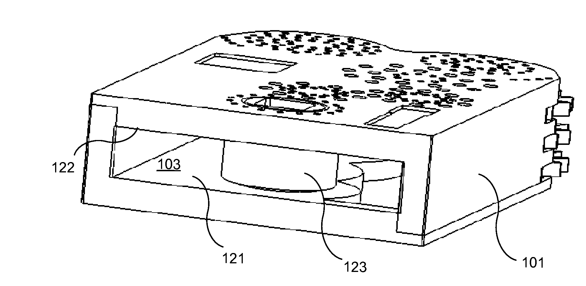
[0162]FIGS. 23A-23D illustrate the working end and drive system of a device in which the drive mechanism includes a belt and pulley. FIG. 23A shows a portion of housing 270, tissue processing elements 271, a portion of gear train 276, belt 272, and pulley 273. FIG. 23B shows a sectional view including belt 272 and a portion of pulley 273 disposed in housing 270. FIG. 23C shows the housing 270 without the belt. FIG. 23D shows a sectional view of housing 270 including a portion of pulley 273, drive mechanism coupler 275, and optional guide wire lumen 274 disposed on the bottom of housing 270. Actuating the belt as shown by the arrows in FIGS. 23A and 23B causes pulley 273 to rotate due to frictional forces between the belt and pulley. The pulley includes a protruding pin (not shown) which couples with drive mechanism coupler 275 to drive the gear train. Rotation of the pulley 273 drives the gear trains which activates the tissue processing elements 271. In some embodiments the belt is...

second embodiment

[0163]FIGS. 24A-C illustrate the working end and drive system of a device in which the drive mechanism is a hydraulic drive mechanism. FIG. 24A shows a portion of the device including a portion of housing 280, tissue processing elements 283, turbine 281 with a plurality of blades 287 coupled to a driving pin (not shown in FIG. 24A), wherein turbine 281 is coupled to drive mechanism coupler 282 via the pin. FIG. 24B is a sectional view of housing 280 in which turbine 281 is disposed. Housing 280 includes fluid channel 288 through which fluid (e.g., liquid or gas) flows in the direction of arrow 284, rotating turbine 281. The fluid exits the housing in the direction of arrow 285 through fluid channel 289. The fluid rotates the blades 287 of turbine 281, which drives the gear train, which activates the tissue processing elements 283. A pump disposed proximal to the housing (e.g. outside the body of the patient and connected to the working end by lumens within a multi-port catheter) and...


PUM


Abstract

The present invention relates generally to the field of micro-scale or millimeter scale devices and to the use of multi-layer multi-material electrochemical fabrication methods for producing such devices with particular embodiments relate to shredding devices and more particularly to shredding devices for use in medical applications. In some embodiments, tissue removal devices are used in procedures to removal spinal tissue and in other embodiments, similar devices are used to remove thrombus from blood vessel.

Description

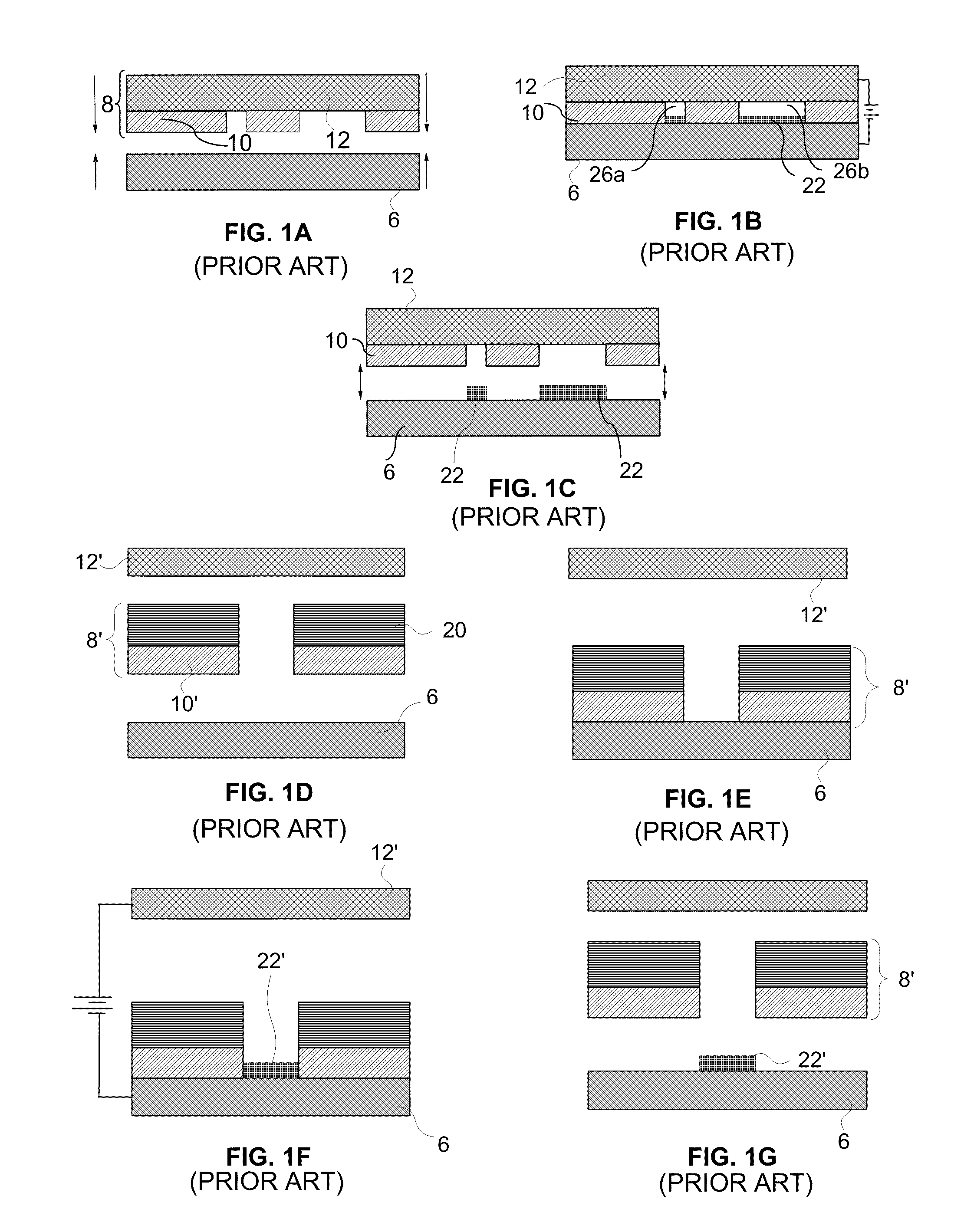
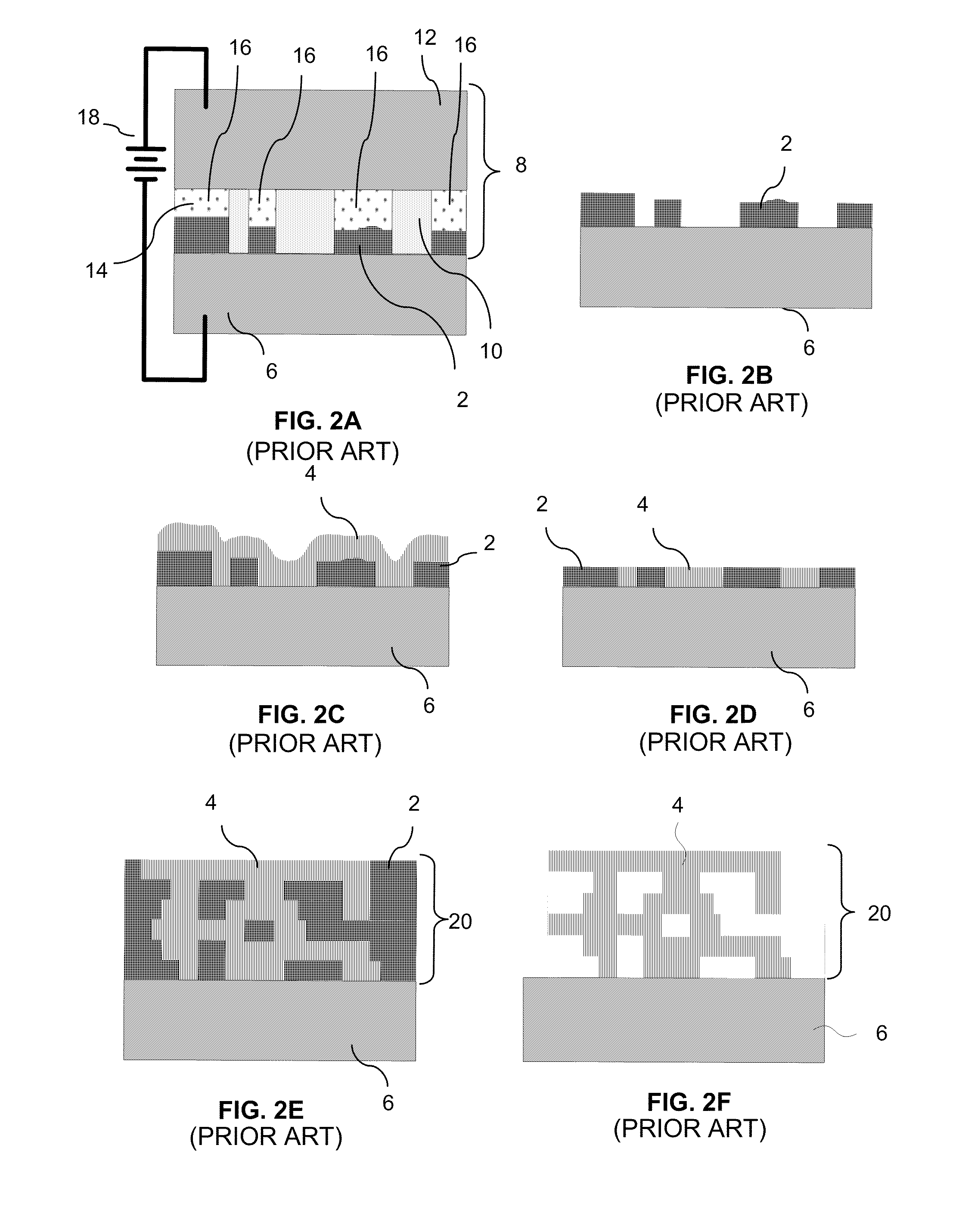
RELATED APPLICATIONS [0001]This application claims benefit of U.S. Provisional Application Nos. 61 / 075,006 (Microfabrica Docket No. P-US222-A-MF), filed Jun. 23, 2008; 61 / 164,864 (P-US222-B-MF), filed Mar. 30, 2009; and 61 / 164,883 (P-US261-A-MF), filed Mar. 30, 2009. Each of these applications is incorporated herein by reference as if set forth in full herein.FIELD OF THE INVENTION [0002]Embodiments of the present invention relate to micro-scale and millimeter-scale shredding devices that may, for example, be used to remove unwanted tissue or other material from selected locations within a body of a patient during a minimally invasive or other medical procedures and in particular embodiments multi-layer, multi-material electrochemical fabrication methods are used to, in whole or in part, form such devices.BACKGROUND OF THE INVENTION Electrochemical Fabrication:[0003]An electrochemical fabrication technique for forming three-dimensional structures from a plurality of adhered layers i...

Claims


Application Information

Patent Timeline
IPC IPC(8): A61B17/00A61B17/58
CPCA61B10/02A61B2017/00261A61B17/221A61B17/32002A61B17/320725A61B17/320758A61B19/5212A61B2017/003A61B2017/00327A61B2017/00526A61B2017/00539A61B2017/00553A61B2017/2212A61B2017/2215A61B2017/320048A61B2017/320775A61B17/1659A61B17/1671A61B17/14A61B90/361B33Y80/00Y10T74/19623A61B2017/320064F16H55/06F16H55/18
Inventor LOCKARD, MICHAEL S.FRODIS, URICOHEN, ADAM L.CHEN, RICHARD T.WU, MING-TINGSCHMITZ, GREGORY P.MILLER, ERIC C.
Owner MICROFAB
Why Eureka
Try Eureka