Roof system and method of fabrication and installation

a technology of foam panel roof and fabrication method, which is applied in the direction of roof covering, floors, building components, etc., can solve the problems of compromising the watertight integrity affecting the performance of the roof system, so as to achieve exceptional insulating value, tremendous uplift strength, and resistance to high wind forces

Inactive Publication Date: 2010-01-21
ANAYA RICHARD J
View PDF9 Cites 11 Cited by
  • Summary
  • Abstract
  • Description
  • Claims
  • Application Information

AI Technical Summary

Problems solved by technology

The use of penetrating fasteners for roof installations presents a number of concerns and potential problems.
In particular, the use of a large number of mechanical fasteners penetrating the roof deck compromises the watertight integrity of the roof system.
Moreover, spot attachment of tiles and shingles using mechanical fasteners results in limited strength against uplift forces experienced during high wind conditions, particularly hurricanes.
Additionally, the weight of conventional roofing tiles, typically made of ceramic, cast concrete or clay, renders them extremely hazardous as projectiles in a hurricane.
All of these foam core roofing panels are designed for installation using penetrating mechanical fasteners, which presents the several problems noted above.
Moreover, the foam core panel systems in the related art do not allow for easily repairing cut or damaged tiles at the installation site in a cost effective manner.
The insulation methods used in conventional steep slope roof structures presents further problems and concerns.
Over time, the high temperature below the tiles, as a result of trapped heat, causes premature failure of the roof system.

Method used


Image

  • Roof system and method of fabrication and installation
  • Roof system and method of fabrication and installation
  • Roof system and method of fabrication and installation

Examples


Embodiment Construction

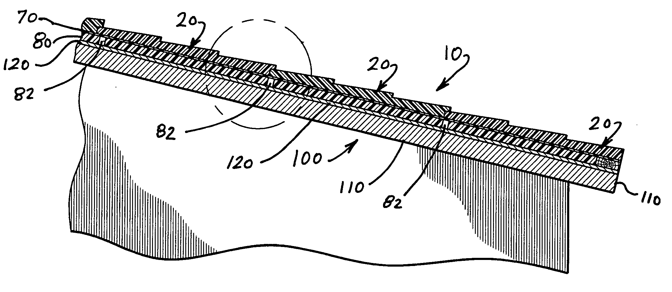
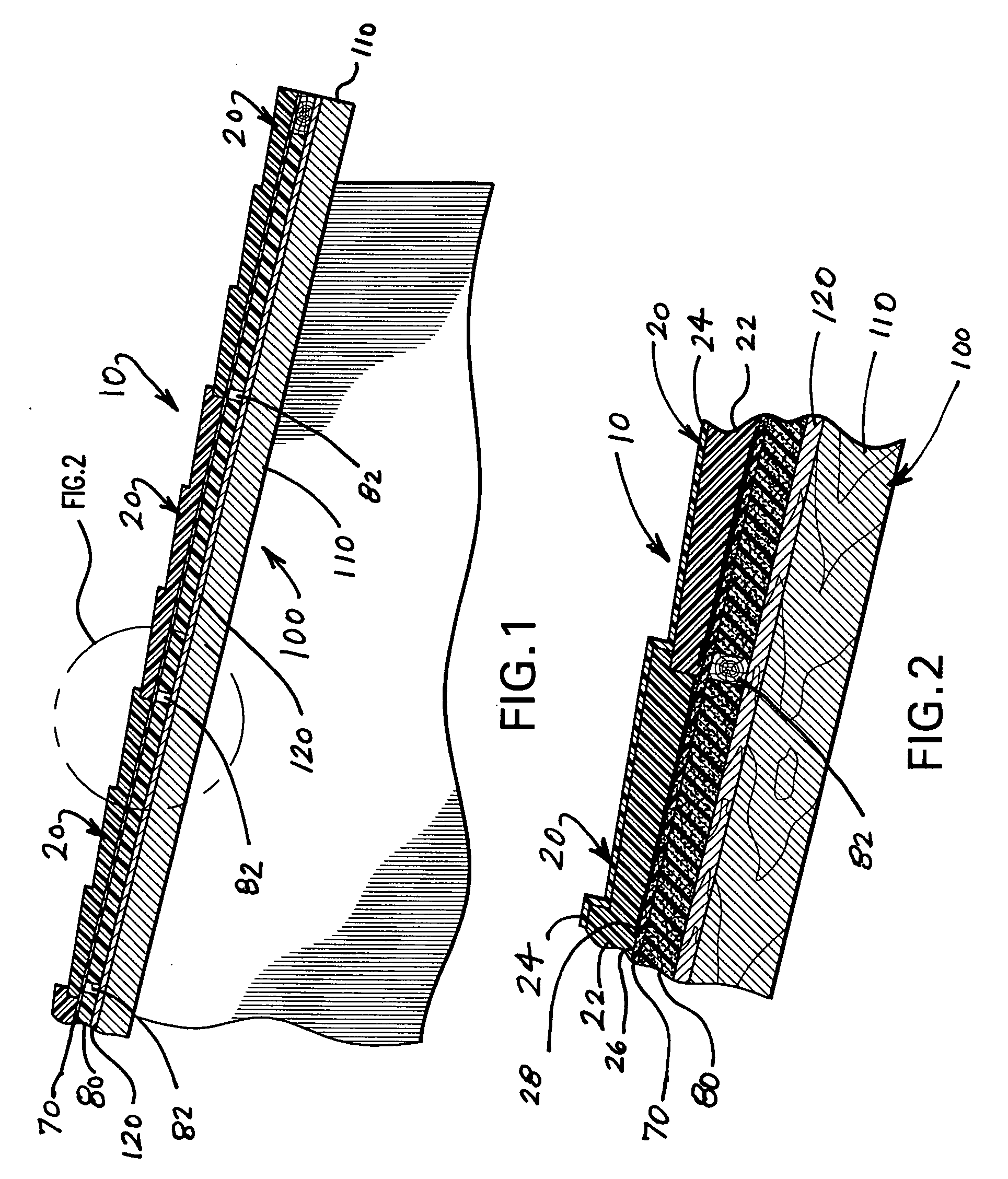
[0033]The roof system of the present invention is shown throughout the several views of the drawings and is generally indicated as 10. The roof system 10 uses individual roofing panels 20 that are molded with a high density polyurethane foam or extruded polystyrene foam core 22. The panels 20 are molded in various sizes, shapes and configurations according to the desired aesthetic appearance of the roof. The molded panels 20 may also be formed as ridge caps, as well as other accessory components for fitting at unique intersections of the roof, terminations with walls, valleys, hips, ridges, etc. The foam core 22 of the roofing panels 20 provides exceptionally high insulating values well beyond that of conventional roofing tiles and shingles. During manufacture, a non-skid primer coat 24, such as a cement acrylic coating composition, is applied to the top surfaces and side edges of the molded panels. To enhance the adhesion characteristics, the bottom side 26 of the molded panels 20 ...


PUM


Abstract

In a roof system having exceptional insulating value, high density polyurethane foam or extruded polystyrene is used to form molded panels of predetermined size, shape and ornamental configuration. A non-skid primer coat is applied to the top surfaces and sides of the panels at the time of manufacture. A fabric layer or polyester mesh may be embedded in the bottom of the molded foam panels to enhance adhesion characteristics. During installation, the panels are set in a layer of low rise foam adhesive that is applied to the underlying roof deck or other surface (e.g., plywood, concrete, roofing felts, or spray foam), thereby avoiding the use of penetrating fasteners while enhancing wind uplift resistance. The panels may include interlocking structure for side-by-side and / or overlapping installation. Edges of the foam panels that need to be cut for fitting at valleys, hips, ridges, etc. are repaired in the field using factory supplied fabric and coating. After complete installation of the panels, a final topcoat composition such as, but not limited to, acrylic epoxy, silicon, or polyurea is applied to seal the roof system and provide a select roof color and desired grade.

Description

BACKGROUND OF THE INVENTION[0001]1. Field of the Invention[0002]This invention relates to foam panel roof systems and, more particularly, to a roof system and method of fabrication and installation of foam roof panels without the use of penetrating fasteners.[0003]2. Discussion of the Related Art[0004]In residential and commercial steep slope roof construction, roofing tiles or shingles are usually installed on top of roofing felts with the use of mechanical fasteners (e.g., nails). Typically, a layer of tar is first applied to the roof deck (e.g., plywood) in order to seal cracks and gaps. The roofing felts are applied using tin tags and nails that penetrate the felts, tar and roof deck. Thereafter, the tiles or shingles are installed using mechanical fasteners that also penetrate the entire roof structure. The use of penetrating fasteners for roof installations presents a number of concerns and potential problems. In particular, the use of a large number of mechanical fasteners pe...

Claims


Application Information

Patent Timeline
Patent Type & Authority Applications(United States)
IPC IPC(8): E04B7/00
CPCE04D1/265E04D3/355E04D3/351E04D1/28
Inventor ANAYA, RICHARD J.
Owner ANAYA RICHARD J
Why Eureka
Try Eureka