
Magnetic body detector

a body detector and magnetic technology, applied in the field of magnetic body detectors, can solve the problems of requiring a lot of cost, affecting the appearance of the body, and a lot of time and cost to start up, so as to reduce the installation cost and improve the appearance

Inactive Publication Date: 2010-01-21
DEED CORP
View PDF4 Cites 20 Cited by
  • Summary
  • Abstract
  • Description
  • Claims
  • Application Information

AI Technical Summary

Benefits of technology

[0026]It is possible to solve the problems of the magnetic interference, the step difference, the cost and the power consumption caused by the Helmholtz coil or the detection coil by using a magnetic sensor with a hall element according to the invention described in Patent Literature 2; However, the problem where a small magnetic body cannot be detected still remains.
[0136]Further, in the present invention, it is possible to reduce installation cost and to improve the appearance.

Problems solved by technology

It is necessary to cool the superconductive magnet down close to absolute 0 of temperature and it take a lot of time and cost to start-up.
In the case of bringing tools, such as a driver made of a magnetic body, such as iron, medical supplies, such as an oxygen bottle or an infusion stand, into the MRI examination room, a magnet attraction accident where these are attracted to a magnet and absorbed into the system may occur.
In order to detach these, the superconductive magnet has to be stopped; however, it takes time to stop and restart the superconductive magnet and the diagnostic task is stopped in the meantime.
Other than the time, it also requires a lot of cost.
In the case of bringing tools or medical supplies made of magnetic body by accident, the magnetic body collides into a patient or a laboratory technician and it may cause injury.
However, it is not guaranteed that the laboratory technicians have perfect knowledge.
Therefore, even if a metal detector is used in a shield door at an examination room of the MRI diagnostic system, it is meaningless.
Therefore, it is meaningless to use this magnetic body detector at airports.

Method used


Image

  • Magnetic body detector
  • Magnetic body detector
  • Magnetic body detector

Examples


Embodiment Construction

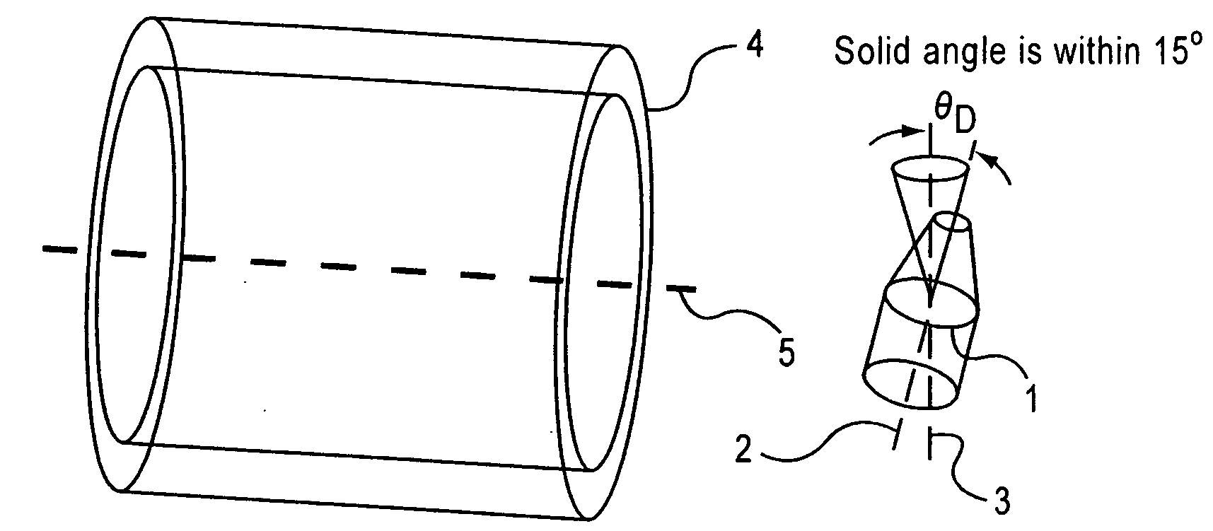
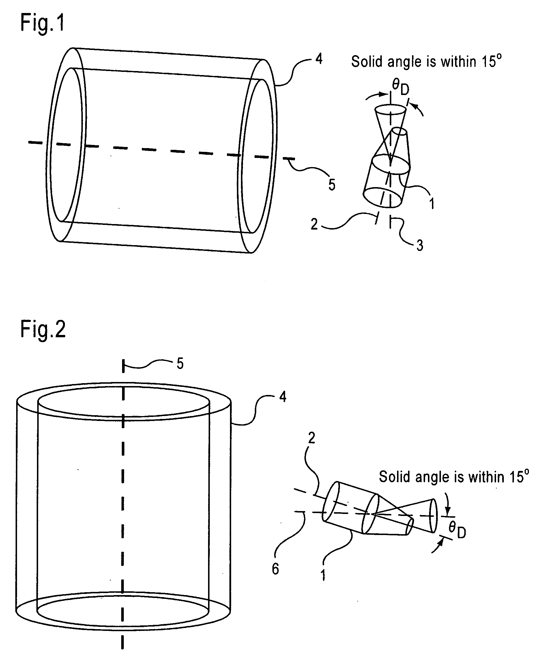
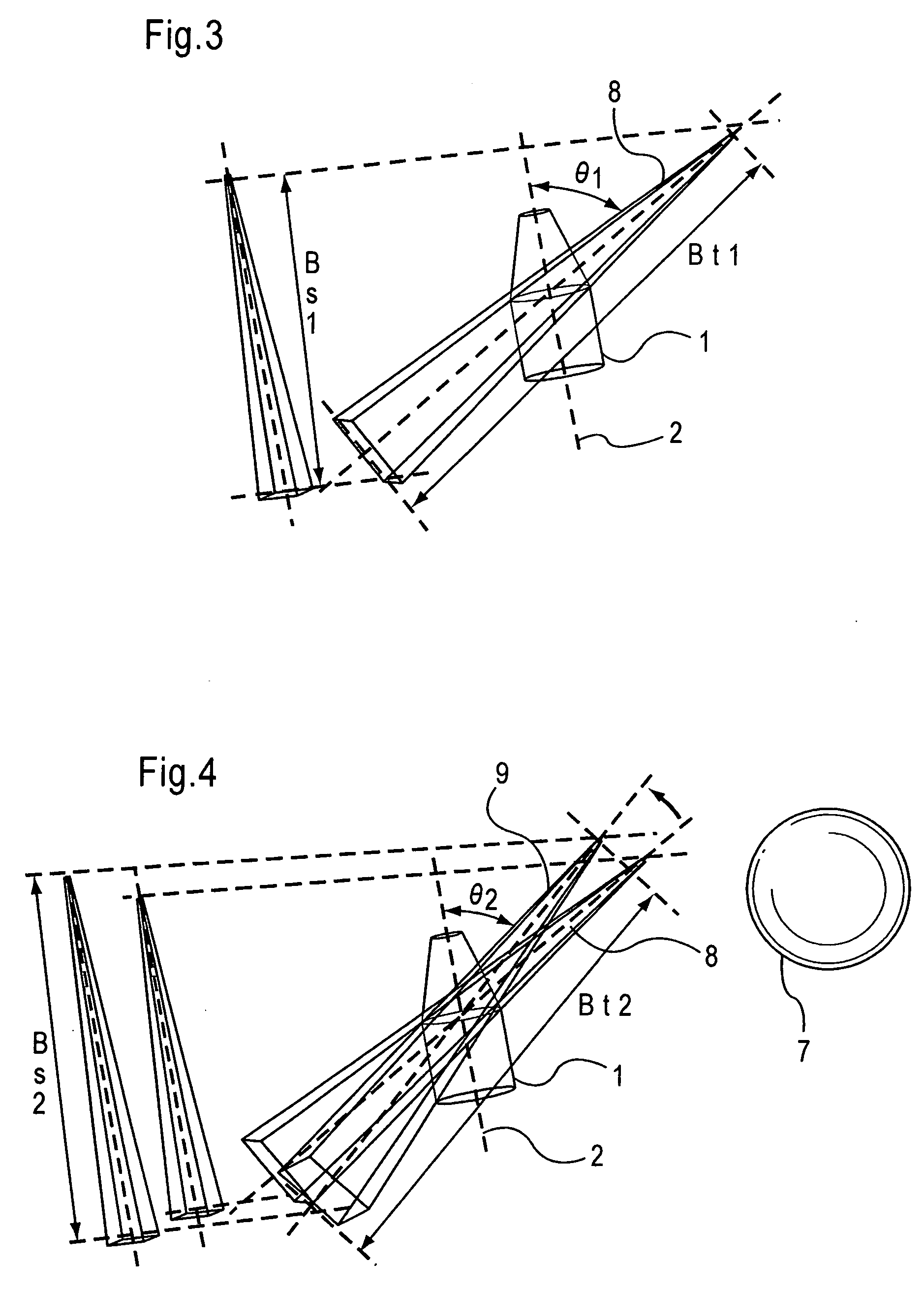
[0230]The magnetic body detector relating to the present invention detects a minute change in magnetic flux density delta B without saturation by setting the detection axis of a magnetic sensor in a horizontal direction or a vertical direction. Further, a plurality of magnetic sensors simultaneously operated and arranged around the periphery of the detection space remove an in-phase component of the change in magnetic flux density delta B due to the movement of the magnetic body in a distance; concurrently, detects magnetic energy generated due to not the magnitude of the change in magnetic flux density delta B to be affected by the movement rate, but by passage, and a presence of a magnetic body is determined. Further, whether a magnetic body is moving toward the gate direction or not is determined according to the rate of magnitude of the change in magnetic flux density delta B detected by the magnetic sensors arranged in the front and rear. In addition, a distance of to a magneti...


PUM


Abstract

To provide a magnetic body detector as a means for warning that a magnetic body enters into a room where a strong magnet, such as an MRI diagnostic system, is installed, whereina magnetic sensor can detect even a small magnetic body without being saturated even in an environment with strong magnetic flux density; andappropriate notification is provided to a user by arithmetic processing for inhibiting the detected value of a magnetic body that does not pass through a gate.[Means for Solving the Problem]By adjusting a solid angle formed with a detection axis of the magnetic sensor and a vertical axis or a horizontal axis to be within 15 degrees, a strong direct-current magnetic flux density to be applied to the detection axis is reduced;a small change in magnetic flux density due to the entry of a small magnetic body is detectable without saturation;the characteristics of a magnetic body that will not pass through the gate is extracted by the magnetic sensors arranged in the front, rear, left and right of the gate; andonly a magnetic body in the vicinity that passes through the gate is regarded as a target for detection by inhibiting magnetic bodies that will not pass through the gate by calculation.

Description

TECHNICAL FIELD[0001]The present invention relates to a magnetic body detector, and specifically relates to a magnetic body detector where a small magnetic body is detectable even under strong magnetic flux density, and that enables the control of an effect due to a movement of the magnetic body outside a detection region.BACKGROUND TECHNOLOGY [0002]As a device crucial to recent medical diagnostics, a magnetic resonance imaging (MRI) diagnostic system is available. This system is a method for imaging internal information within a living body by utilizing a nuclear magnetic resonance phenomenon, and requires a strong magnet. Recently, for the purpose of improvement of resolution power and processing speed, an MRI diagnostic system using an extremely strong magnet, such as 1.5 T (tesla) or 3 T, is being developed. For such strong a magnet, a superconductive magnet is generally used. It is necessary to cool the superconductive magnet down close to absolute 0 of temperature and it take ...

Claims


Application Information

Patent Timeline
IPC IPC(8): G01R33/16
CPCG01V3/08G01R33/288
Inventor MASUBUCHI, SHINICHIUCHIDA, HIROSHI
Owner DEED CORP
Learn More