
Film forming method and apparatus, and storage medium

a film and film technology, applied in the field of thin film forming, can solve the problems of difficult wiring, low use efficiency of the source gas that contributes to film formation, and low efficiency of the source gas, so as to achieve high film forming rate, high source gas price, and high use efficiency of source material.

Inactive Publication Date: 2010-01-21
TOKYO ELECTRON LTD
View PDF6 Cites 2 Cited by
  • Summary
  • Abstract
  • Description
  • Claims
  • Application Information

AI Technical Summary

Benefits of technology

The present invention provides a method and apparatus for forming a thin film on a substrate by causing a chemical reaction of a source gas on the substrate. The method includes steps of mounting the substrate in a processing chamber, adsorbing the source gas onto a surface of an adsorption / desorption member, and heating the substrate to a higher temperature than the adsorbed gas. The invention aims to increase efficiency of film formation by reducing the amount of source gas consumed during the process. The apparatus includes a processing chamber, an adsorption / desorption member, and a control unit for controlling the temperature of the substrate and the adsorption / desorption member. The method and apparatus can be used in various film forming processes such as atomic layer deposition and chemical vapor deposition.

Problems solved by technology

However, since an opening dimension of a wiring groove or hole formed on a substrate becomes smaller to meet the recent demands for high integration of devices, plating solution cannot be supplied into the opening in the conventional plating method so that it makes difficulty in forming wiring.
Since, however, most of the source gas is exhausted, the use efficiency of the source gas that contributes to the film formation is only a few percent.
The unnecessary waste of large amount of the source material is cost-ineffective due to its high cost, and hinders effective utilization of the source material.
Further, the CVD apparatus requires a high-volume vacuum pump capable of exhausting a large amount of source gas despite that such vacuum pump is considerably high-priced.
Moreover, a large exhaust amount of the source gas that produces deposits or products accelerates deterioration of the vacuum pump by the source gas, which increase the maintenance cost.
However, this technique cannot solve the problems of the present invention.

Method used


Image

  • Film forming method and apparatus, and storage medium
  • Film forming method and apparatus, and storage medium
  • Film forming method and apparatus, and storage medium

Examples


Embodiment Construction

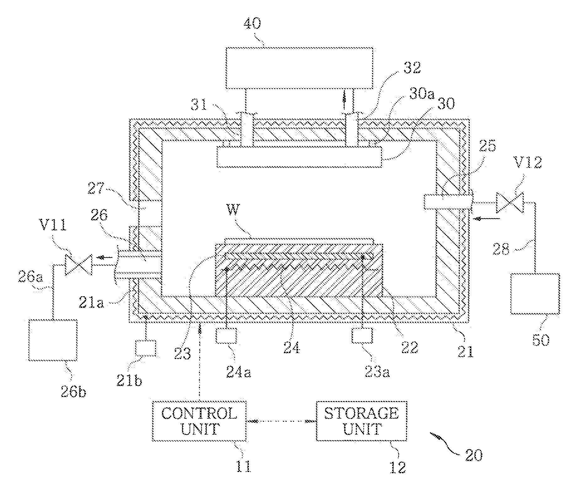
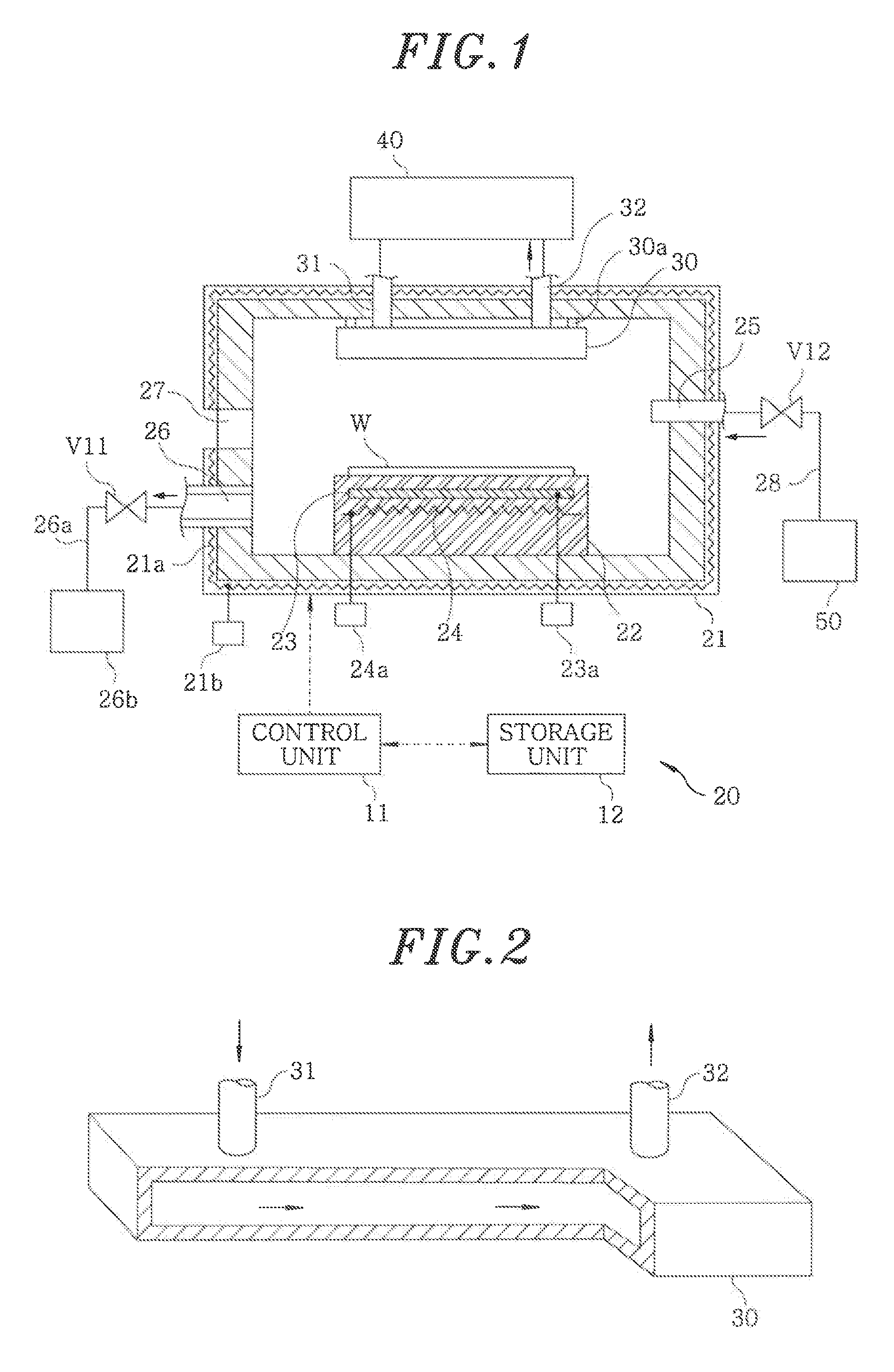
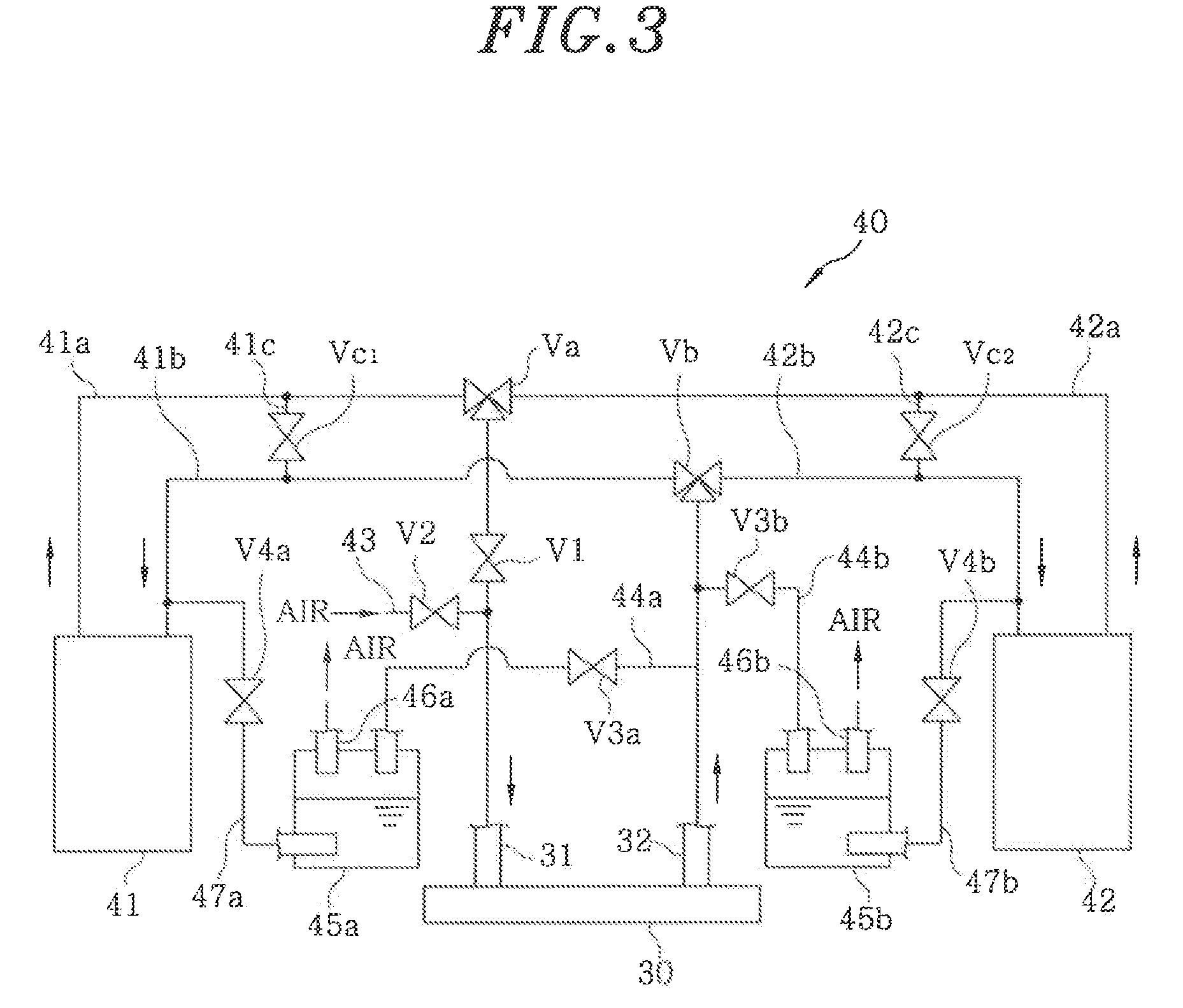
[0039]A film forming apparatus 20 for performing the film forming method in accordance with the present invention will be explained with respect to FIGS. 1 to 4. The film forming apparatus 20 includes a processing chamber 21 and a mounting table 22 provided at a lower portion of the processing chamber 21. The processing chamber 21 is provided with a heater 21a serving as a first temperature control unit for controlling a temperature of an inner wall of the processing chamber 21, and the heater 21a is connected to a power supply 21b.

[0040]An electrostatic chuck 23 for electrostatically attracting and holding a substrate, e.g., a semiconductor wafer (hereinafter, referred to as a “wafer W”), is buried in the mounting table 22, and is connected to a power supply 23a. The mounting table 22 is provided with a heater 24 serving as a second temperature control unit for controlling a temperature of the wafer W, and the heater 24 is connected to a power supply 24a. Moreover, the heater 24 c...


PUM

PropertyMeasurementUnit
temperatureaaaaaaaaaa
temperaturesaaaaaaaaaa

Abstract

A method for film formation is provided that can significantly suppress the amount of a source gas consumed in the formation of a copper film on a substrate by supplying a gas of a metallic source material complex, for example, copper acetate, produced by the sublimation of a solid source material, as a source gas to the substrate to cause a chemical reaction of the source gas. A source gas produced by the sublimation of a solid source material is supplied into a processing chamber, and the source material is adsorbed as a solid onto an adsorption / desorption member within the processing chamber. Next, the source gas supply and exhaust are stopped, and the processing chamber is brought to the state of a closed space. Thereafter, the substrate is heated, and the source material is chemically reacted on the substrate to form a thin film on the substrate.

Description

[0001]This application is a Continuation Application of PCT[0002]International Application No. PCT / JP2008 / 054649 filed on Mar. 13, 2008, which designated the United States.FIELD OF THE INVENTION[0003]The present invention relates to a technique for forming a thin film by causing a chemical reaction of a source gas on a substrate.BACKGROUND OF THE INVENTION[0004]There has been used a plating method for forming wiring on a substrate. However, since an opening dimension of a wiring groove or hole formed on a substrate becomes smaller to meet the recent demands for high integration of devices, plating solution cannot be supplied into the opening in the conventional plating method so that it makes difficulty in forming wiring.[0005]Hence, there has been examined a method for forming wiring by a CVD (Chemical Vapor Deposition) method described in, e.g., Patent Document 1, instead of the plating method. In this method, a metal film is formed by causing a chemical reaction of a source gas o...

Claims


Application Information

Patent Timeline
Patent Type & Authority Applications(United States)
IPC IPC(8): C23C16/44C23C16/52C23C16/00
CPCC23C16/18C23C16/448C23C16/4481H01L21/76877C23C16/45593H01L21/28556C23C16/455C23C16/52
Inventor ITOH, HITOSHI
Owner TOKYO ELECTRON LTD
Learn More