
Method of making rollers with a fine pattern

a technology of making rollers and patterns, applied in the field of making rollers, can solve the problems of reducing reducing the service life of the roller, so as to achieve the effect of increasing the life of the roller

Inactive Publication Date: 2010-01-21
LEE TAI CHEUNG
View PDF9 Cites 10 Cited by
  • Summary
  • Abstract
  • Description
  • Claims
  • Application Information

AI Technical Summary

Benefits of technology

[0007]The objective of the present invention is to increase the roller lifetime and to produce a high-precision pattern thereon. The invention provides a new manufacturing method. According to the method, the roller surface is formed with a ceramic layer to prevent the roller from damages due to erosion. Laser is then employed to form a high-precision pattern on the ceramic layer.

Problems solved by technology

Due to the material characteristics of the steel roller and the limitation of mold casting, the roller can only be formed with helical or quadrangular patterns.
The best precision of the pattern thus made cannot satisfy the requirements of modern LCD fabrication.
Therefore, the pattern is often deformed after long time uses.

Method used


Image

  • Method of making rollers with a fine pattern
  • Method of making rollers with a fine pattern
  • Method of making rollers with a fine pattern

Examples


Embodiment Construction

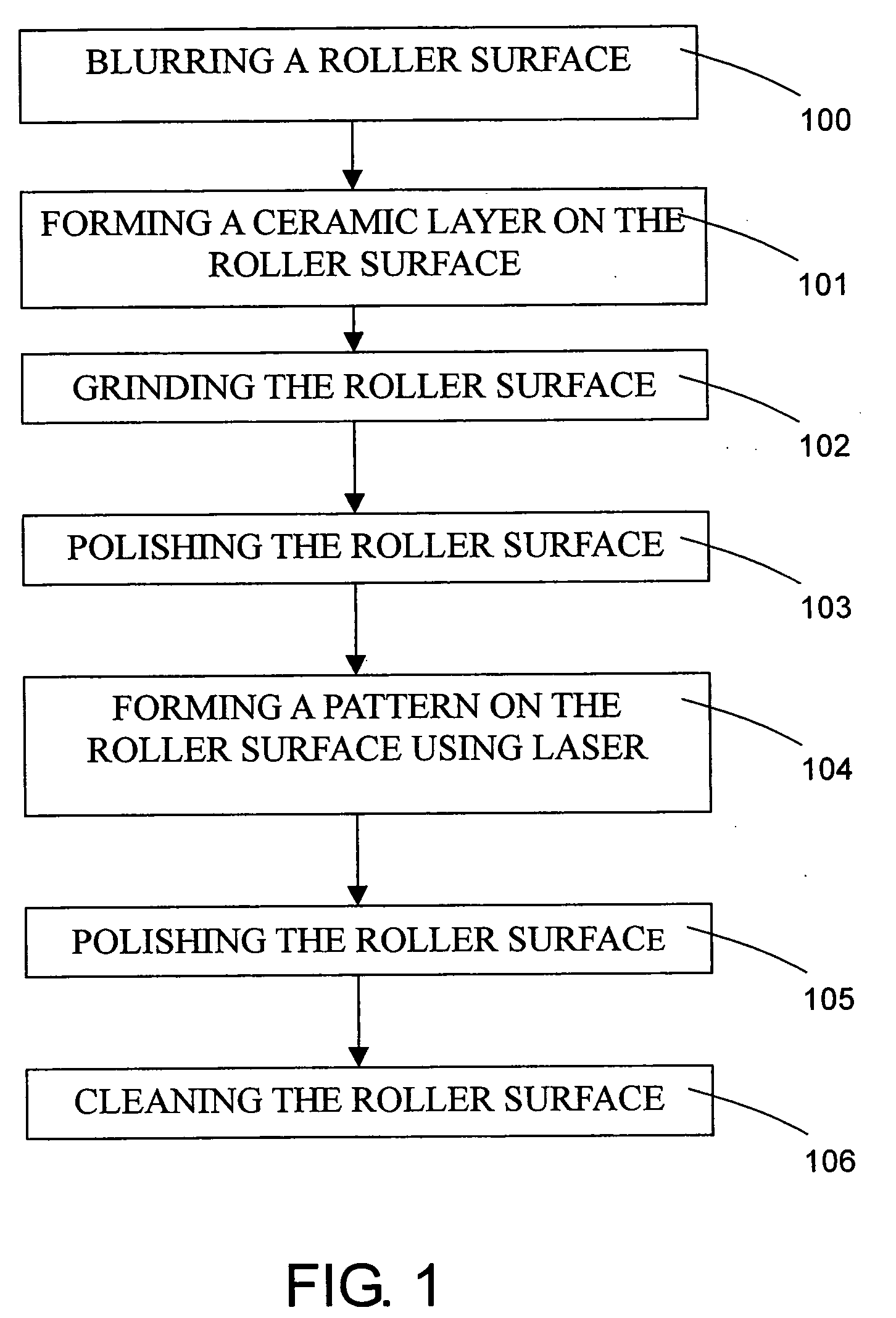
[0021]With reference to FIG. 1, a method in accordance with the present invention includes the following acts: blurring a roller surface (100), forming a ceramic layer on the roller surface (101), grinding the roller surface (102), polishing the roller surface (103), forming a pattern on the roller surface using laser (104), further polishing the roller surface (105) and cleaning the roller surface (106).

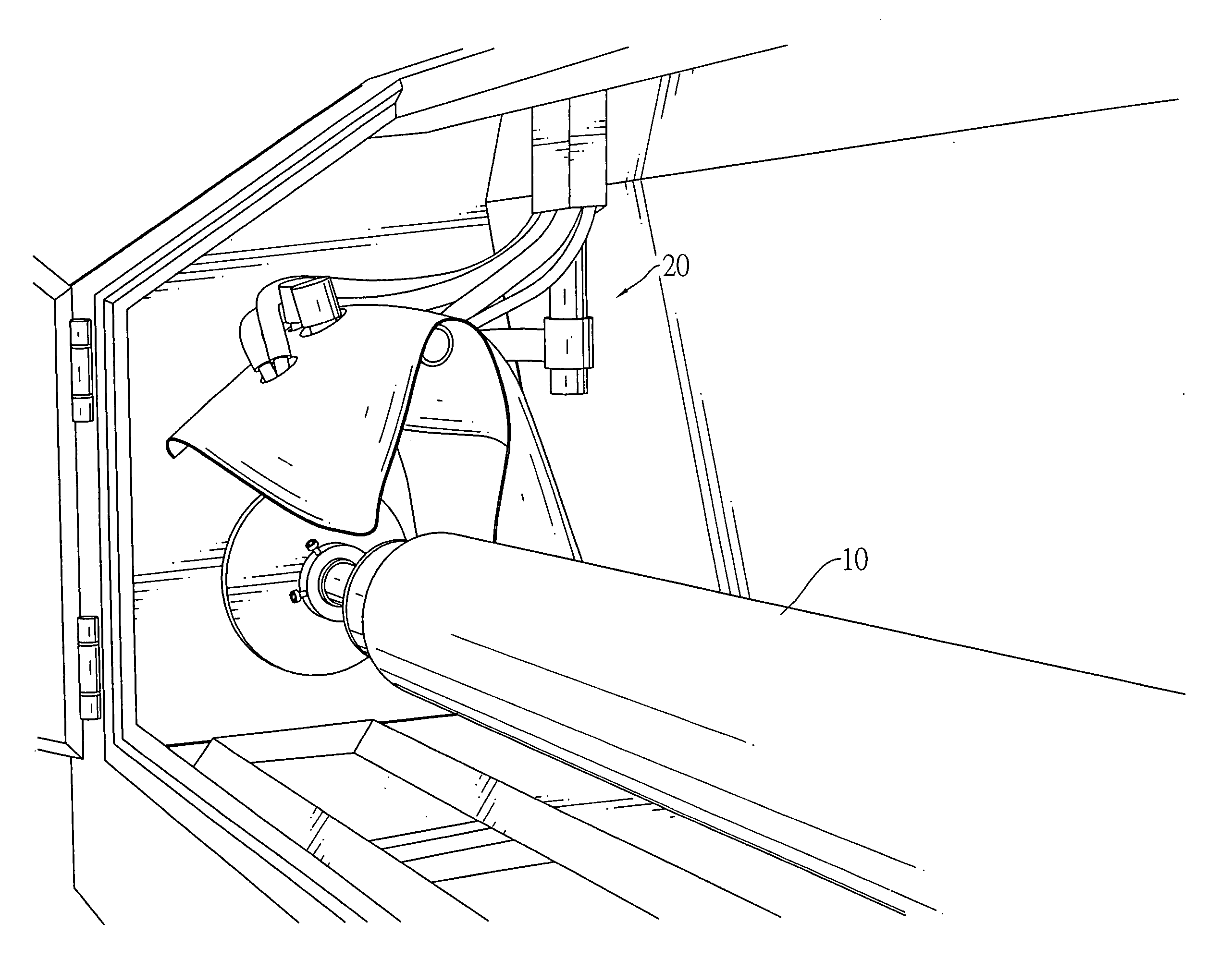
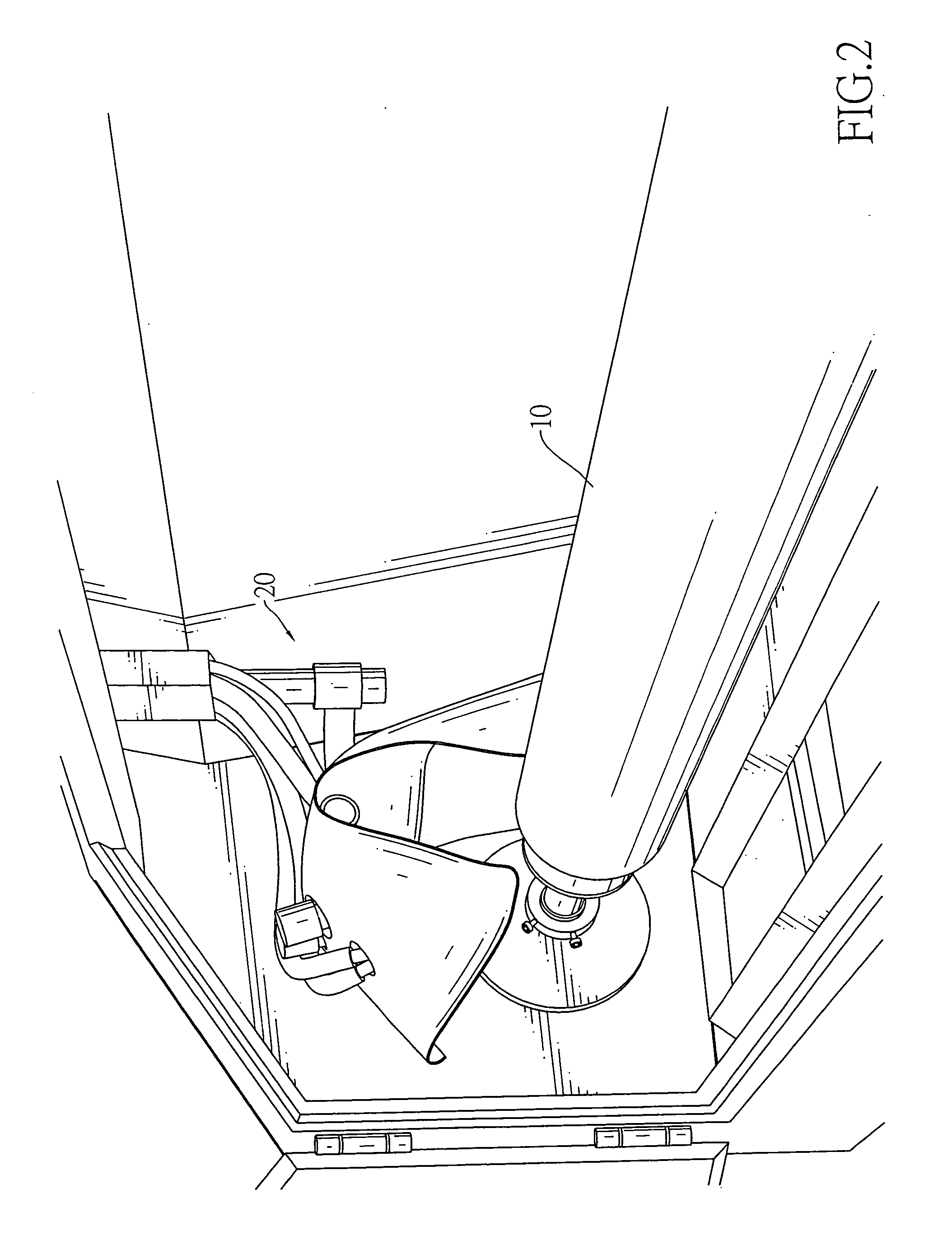
[0022]With reference to FIG. 2 for the act of blurring the roller surface (100), the roller surface is blurred so that it becomes rough and non-specular. The blurring process can be achieved using a sand blaster 20. Compressed air pushes polishing sands to hit the surface of a metal roller 10, forming a blurred surface thereon.

[0023]With reference to FIG. 3 for the act of forming a ceramic layer on the roller surface (101), the roller 10 is mounted on a plasma spray coating machine 30. The plasma spray coating technique is used to cast an auxiliary bond layer on the roller 10. Ceram...


PUM

PropertyMeasurementUnit
Fractionaaaaaaaaaa
Fractionaaaaaaaaaa
Fractionaaaaaaaaaa

Abstract

A method of making rollers with a fine pattern has the acts of casting a ceramic layer onto a roller surface, grinding and polishing the roller surface, forming a pattern on the roller surface with laser, and cleaning the roller surface. Therefore, the roller thus made has a pattern with higher precision than the conventional method of mold casting. Since the roller surface has a ceramic layer that has better resistance to erosion than steel, the roller has a longer lifetime.

Description

BACKGROUND OF THE INVENTION[0001]1. Field of the Invention[0002]The invention relates to a method of making a roller, in particular, to a method of making a roller with a fine pattern.[0003]2. Description of Related Art[0004]A patterned roller has applications in various technical fields. For example, such a roller can be used to make laser hologram label, transfer patterns on anti-counterfeiting labels or an anilox roller used in the manufacturing of liquid crystal displays (LCD). Normally, a roller is formed with the desired pattern and then transfers the pattern on to a target object. When making the patterned roller, a surface of a steel roller is first ground to remove unsmooth stuff thereon. The roller surface is then polished to produce a specular surface. Afterwards, a mold is used to cast the desired pattern on the roller surface. Finally, the roller surface is cleaned to ensure the quality of subsequent products.[0005]Due to the material characteristics of the steel roller...

Claims


Application Information

Patent Timeline
IPC IPC(8): B05D3/06
CPCB23K26/408B41C1/05B41C1/184B41N1/20C23C4/02B41N2207/10C23C4/105C23C4/18B41N7/06B41N2207/02C23C4/06B23K26/40C23C4/11B23K2103/52
Inventor LEE, TAI-CHEUNG
Owner LEE TAI CHEUNG
Learn More