Fuel cell
- Summary
- Abstract
- Description
- Claims
- Application Information
AI Technical Summary
Benefits of technology
Problems solved by technology
Method used
Image

Examples
first exemplary embodiment
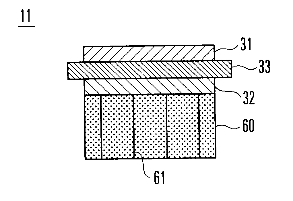
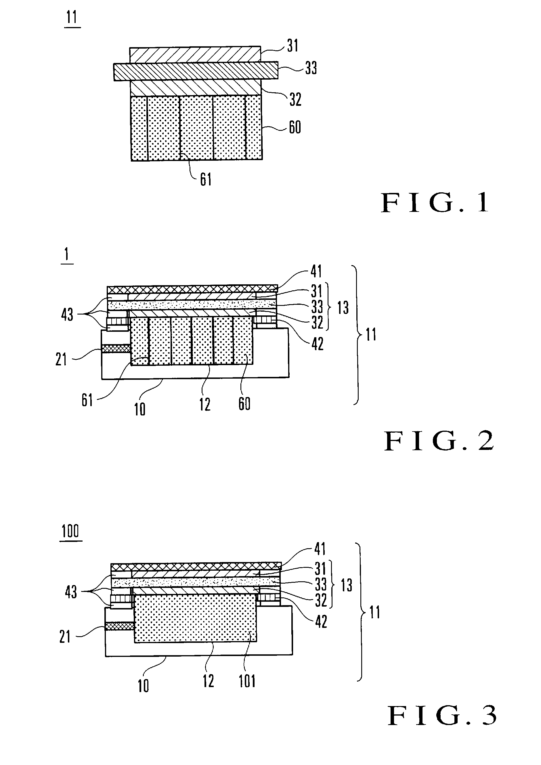
[0035]As shown in FIG. 1, a fuel cell 11 forming a fuel cell system according to the first exemplary embodiment includes at least a polymer electrolyte membrane 33, a cathode 31 formed on one surface of the polymer electrolyte membrane 33, an anode 32 formed on the other surface, and a wicking member 60 formed on that surface of the anode 32 which is opposite to the surface facing the polymer electrolyte membrane 33.
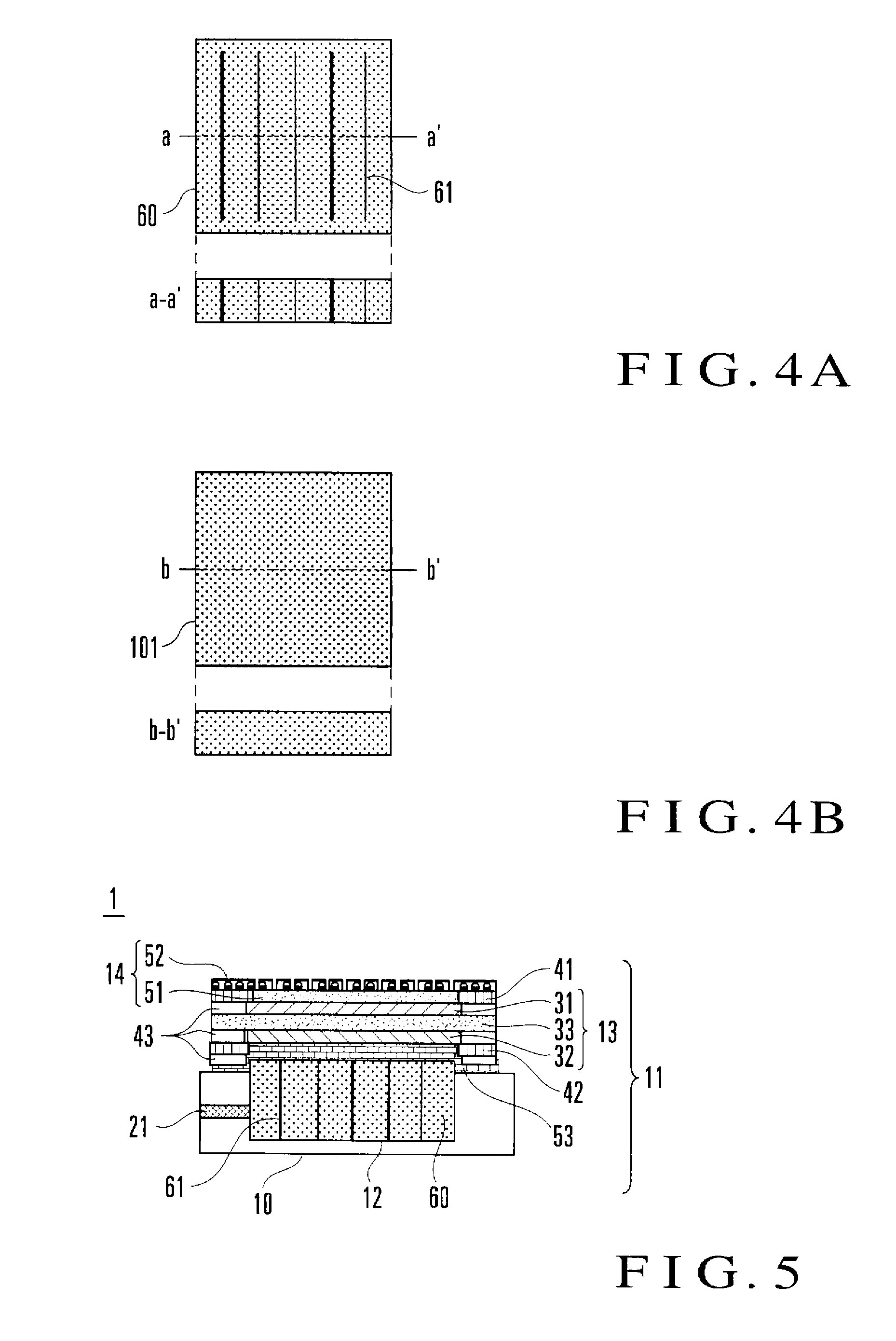
[0036]The wicking member 60 is made of a known fuel retaining agent such as woven fabric, unwoven fabric, a fiber mat, a fiber web, or a foamed polymer, and cut lines 61 are formed in the thickness direction.
[0037]The fuel cell 11 as described above is a direct methanol fuel cell directly using an aqueous methanol solution as liquid fuel. When this liquid fuel is supplied to the anode 32 via the wicking member 60, the reaction represented by formula (1) or (2) described previously occurs in the cathode 31 or anode 32, thereby generating electric power. Note that the basi...
second exemplary embodiment
[0039]The second exemplary embodiment of the present invention will now be explained. Note that in this exemplary embodiment, the same names and reference numerals as in the first exemplary embodiment denote the same constituent elements, and a repetitive explanation will be omitted.
[0040]
[0041]As shown in FIG. 2, a fuel cell 11 forming a fuel cell system according to this exemplary embodiment includes a fuel tank unit 12 having a frame 10 as a recessed member, and a wicking member 60 is inserted into the fuel tank unit 12. In practice, the frame 10 has a structure capable of storing liquid fuel. Also, a fuel injection port 21 for injecting fuel is formed in the frame 10, so the fuel can be replenished any time. On the frame 10, an MEA 13 is set as it is sandwiched between collectors. More specifically, an anode collector 42 and cathode collector 41 are respectively positioned on the sides of an anode 32 and cathode 31, and sandwich the MEA 13, thereby performing current collection....
first example
[0085]First, the structure of a fuel cell 11 according to the first example will be explained below.
[0086]Initially, fine catalyst-carrying carbon particles were prepared by causing carbon particles (ketjen black EC600JD manufactured by LION) to carry, at a weight ratio of 50%, fine platinum particles having a particle size of 3 to 5 nm. 5 wt % of a Nafion (registered trademark) solution (DE521 manufactured by Du Pont) were added to 1 g of the fine catalyst-carrying carbon particles, and catalyst paste for cathode formation was obtained by agitating the mixture. Carbon paper (TGP-H-120 manufactured by TORAY) as a base was coated with 1 to 8 mg / cm2 of the catalyst paste, and the catalyst paste was dried, thereby manufacturing a 4 cm×4 cm cathode 31. On the other hand, catalyst paste for anode formation was obtained under the same conditions as those for producing the catalyst paste for cathode formation described above, except that fine platinum (Pt)-ruthenium (Ru) alloy particles (t...
PUM
 Abstract
Description
Claims
Application Information
 - R&D Engineer
- R&D Manager
- IP Professional
- Industry Leading Data Capabilities
- Powerful AI technology
- Patent DNA Extraction
Browse by: Latest US Patents, China's latest patents, Technical Efficacy Thesaurus, Application Domain, Technology Topic.
© 2024 PatSnap. All rights reserved.Legal|Privacy policy|Modern Slavery Act Transparency Statement|Sitemap