
Sorting system

a sorting system and sorting technology, applied in sorting, mechanical conveyors, instruments, etc., can solve the problems of labor intensive, less accurate process, and reduced melt quality, and achieve the effect of more accura

Inactive Publication Date: 2010-01-21
INNOV X SYST
View PDF23 Cites 45 Cited by
  • Summary
  • Abstract
  • Description
  • Claims
  • Application Information

AI Technical Summary

Benefits of technology

[0014]It is a further object of this invention to provide such a sorting system and method which is more accurate.

Problems solved by technology

The problem is that items like electric motors present in the waste stream include both steel and copper and these “meatballs” are attracted to the magnet.
If copper is added to the melt, the quality of the melt is severely reduced as copper weakens the resulting recycled steel.
The result is a labor intensive, less accurate process, and the possibility that mistakes are made in which case copper or other undesirable elements contaminate the melt.
In cases of glass or plastic, there is often no removal of undesirables performed because the material of interest cannot be visually identified, or it is not economically feasible to do so even in low labor cost regions.
Existing manually operated x-ray florescence (XRF) analysis techniques have not been successfully adapted for high volume, automated scrap metal sorting.
The sorting environment is extremely harsh and dirty, the shredded waste varies in size, mass, and composition, and any viable system would have to cost less and have a reliability and exhibit a throughput greater than the existing manual picking process.
Adapting an x-ray system to replace the manual process includes several technological challenges.
Analyzing the scrap items traveling at such high speeds can be very difficult.
The “detection accuracy” is that the XRF system may not detect enough x-rays to make a statistically significant decision that a certain type of metal is present.

Method used


Image

  • Sorting system
  • Sorting system
  • Sorting system

Examples


Embodiment Construction

[0034]Aside from the preferred embodiment or embodiments disclosed below, this invention is capable of other embodiments and of being practiced or being carried out in various ways. Thus, it is to be understood that the invention is not limited in its application to the details of construction and the arrangements of components set forth in the following description or illustrated in the drawings. If only one embodiment is described herein, the claims hereof are not to be limited to that embodiment. Moreover, the claims hereof are not to be read restrictively unless there is clear and convincing evidence manifesting a certain exclusion, restriction, or disclaimer.

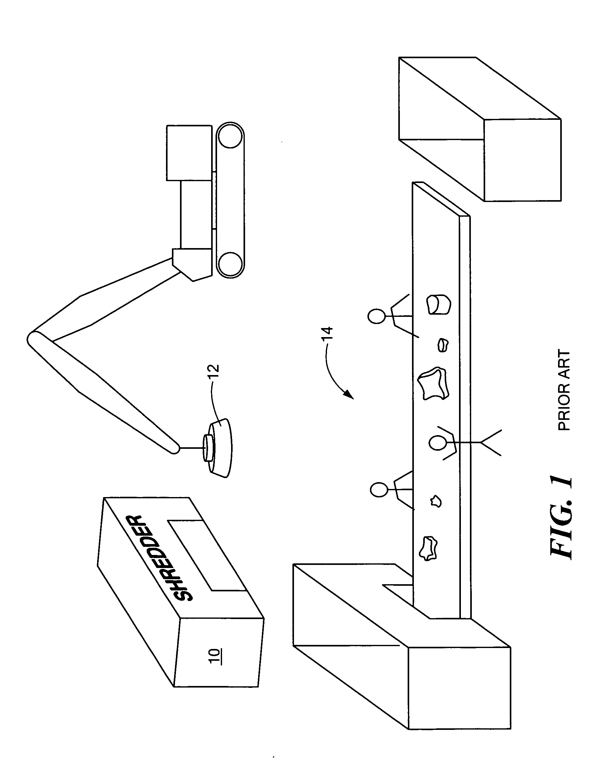
[0035]FIG. 1 shows a prior art sorting operation as described in the background section above wherein items are shredded in shredder 10 and the shredded metal waste is picked up by magnet 12 for delivery to manual sorting operation 14 where workers (“pickers”) remove “meatballs” from the waste stream. If these copper bearin...


PUM


Abstract

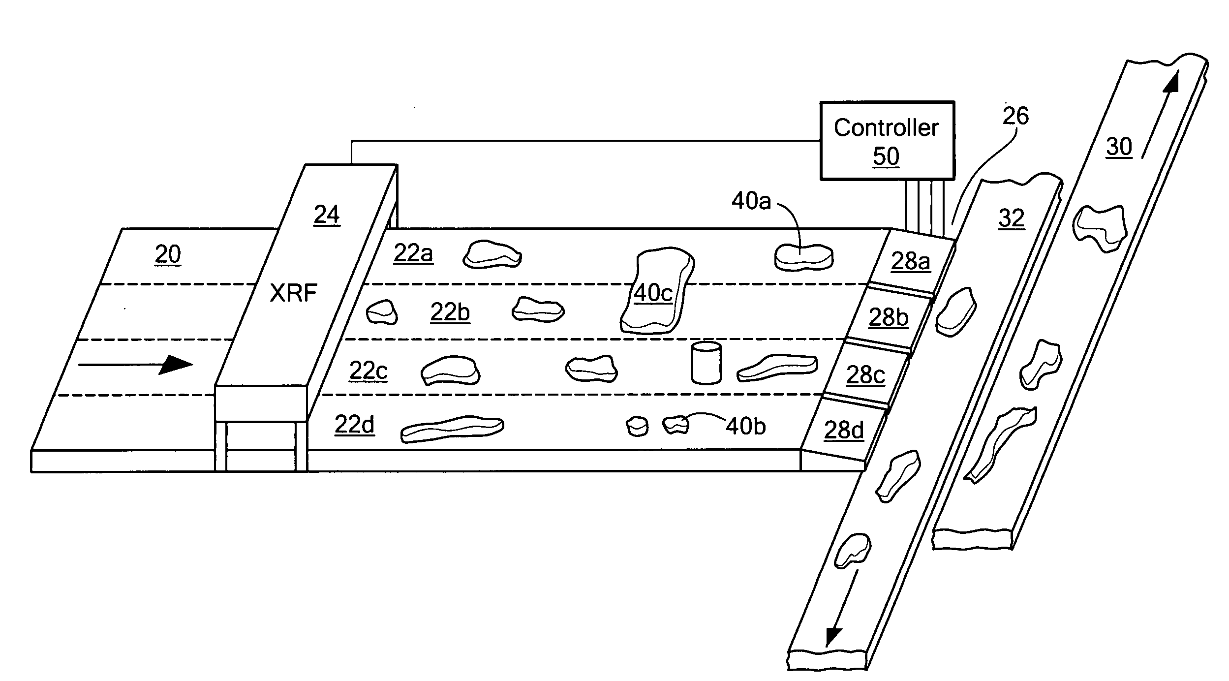
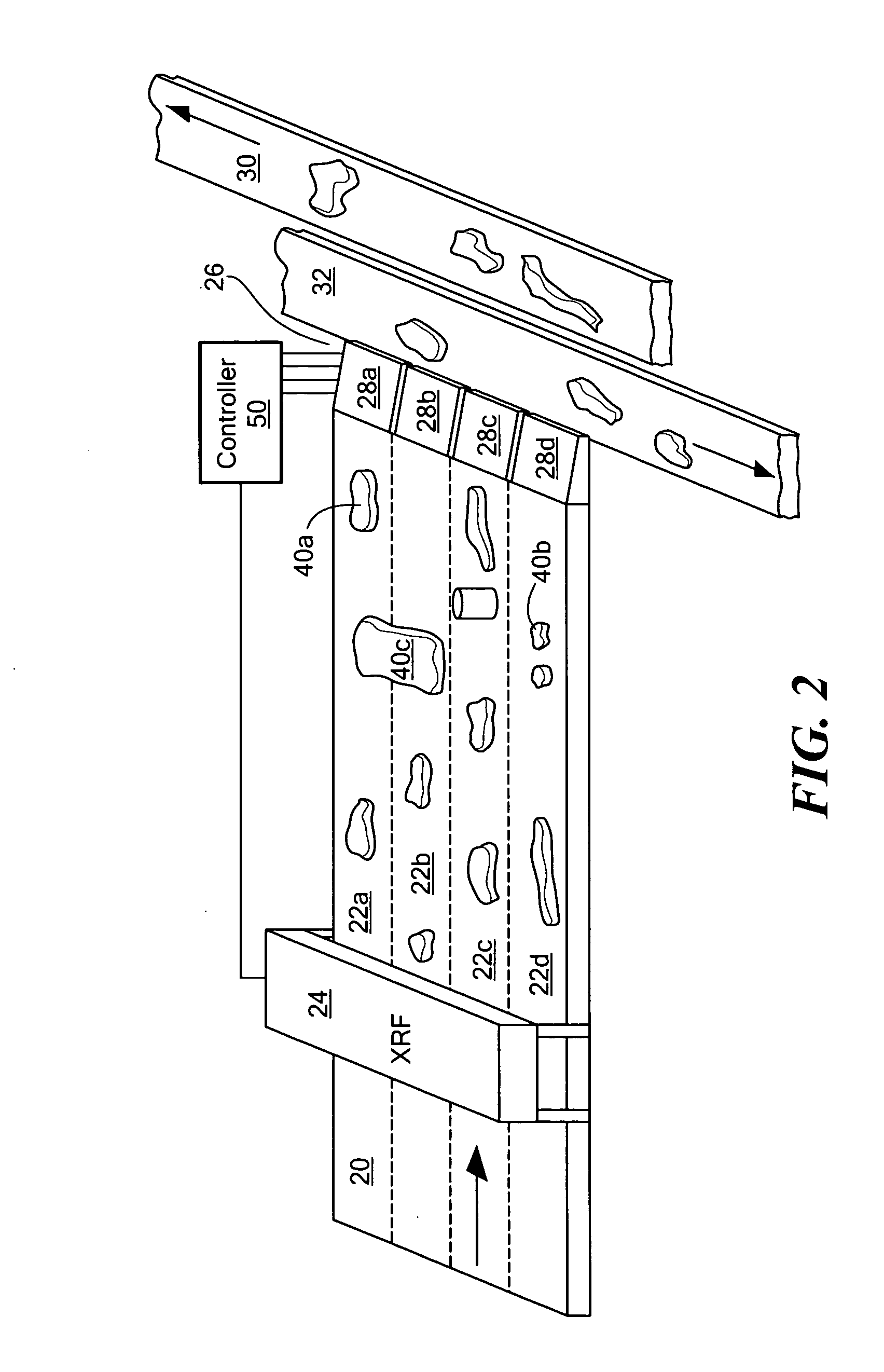
A sorting system and method with a conveyance for transporting items to be sorted at a predetermined speed. An XRF spectrometer subsystem includes at least one x-ray source directing x-ray energy at an item carried by the conveyance and a detector responsive to x-rays emitted by the item and producing a spectral signal characterizing a leading edge of the item and a trailing edge of the item. A diverter subsystem downstream of the XRF subsystem is for diverting sorted items. An electronic processing subsystem is responsive to the detector signal and is configured to determine if the item is to be diverted based on the elemental makeup of the item from its x-ray spectrum. The same processing subsystem is also configured to calculate the position of the item on the conveyance based on the detector signal and together with the predetermined speed of the conveyance controlling the diverter subsystem to divert selected items.

Description

FIELD OF THE INVENTION[0001]This invention relates to sorting systems, and in one particular embodiment, to a scrap metal sorting system.BACKGROUND OF THE INVENTION[0002]Sorting systems are used to divert undesirable items in a waste stream from the desirable items. Some systems are automatic or semiautomatic and employ x-ray technology to classify the various items. See, for example, U.S. Pat. Nos. 6,266,390; 6,519,315; and 6,888,917. Other similar systems are disclosed in U.S. Pat. Nos. 5,663,997; 4,848,590; 5,236,092; 5,314,072; 5,260,576; and European Patent No. EPO 096092.[0003]In some industries, sorting is still performed manually. For example, in the scrap metal industry, vehicles, washers, dryers, and other large items are shredded and then a magnet is used to retrieve steel (the “ferrous” fraction) from the shredded waste. The steel is then melted down for recycling. The problem is that items like electric motors present in the waste stream include both steel and copper an...

Claims


Application Information

Patent Timeline
IPC IPC(8): B65G43/08G06F17/00
CPCB07C5/346B07C2501/0036B07C2501/0054
Inventor HUBBARD-NELSON, BRADLEYSACKETT, DONEGAN, JOHN FRANCIS
Owner INNOV X SYST
Learn More