
Soiling measurement system for photovoltaic arrays

Active Publication Date: 2017-04-13
ATONOMETRICS
View PDF1 Cites 32 Cited by
  • Summary
  • Abstract
  • Description
  • Claims
  • Application Information

AI Technical Summary

Benefits of technology

The patent is about a system that measures the amount of power lost due to solar module soiling in actual or prospective solar power plants. The system uses a clean reference module that is placed in the same conditions as the soiled modules, which helps to account for non-uniform soiling and allows for the separation of soiling-related losses from other losses. The clean reference module is designed to be easily maintained between measurements, which maximizes its lifespan. The disclosed technology and practices improve upon existing methods by providing more accurate measurements and economical apparatus with minimized maintenance requirements.

Problems solved by technology

Among the most significant meteorological conditions affecting solar power plant performance are the solar irradiance at the site, the ambient temperature at the site, and the accumulation of dust and dirt or other contaminants on the PV modules.
Soiling reduces the solar irradiance transmitted to the active area of the PV modules, thus reducing power output.
However, this method assumes that all efficiency losses are due to environmental factors and that there is no underlying fault or degradation in the solar power plant performance that would also result in efficiency loss.
This method also does not apply to assessing soiling-related power losses from prospective solar power plants prior to construction.
However, since this method estimates power loss from measurements of short-circuit current, i.e. from effective irradiance reaching the module, it will yield inaccurate results in certain situations, principally when the soiling is accumulated non-uniformly across the surfaces of the modules.
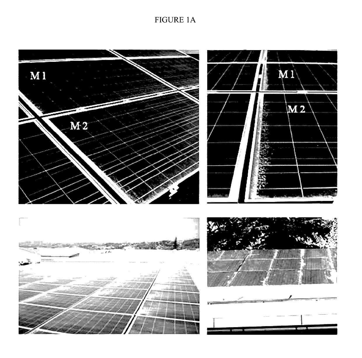
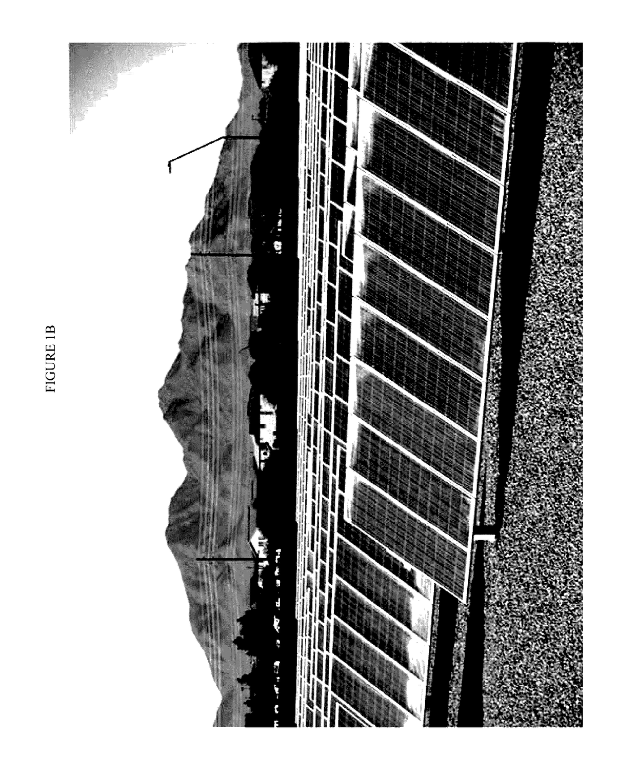
Such non-uniform distributions of soiling frequently occur due to the influences of module orientation, wind, rain, and gravity, often resulting in predominant soiling across one edge or another localized region of the modules, as illustrated in photographs of soiled photovoltaic arrays shown in FIGURE LA and FIG. 1B.
However, this requires the availability of water and / or on-site water storage, which may have associated costs, especially in remote or desert sites.

Method used


Image

  • Soiling measurement system for photovoltaic arrays
  • Soiling measurement system for photovoltaic arrays
  • Soiling measurement system for photovoltaic arrays

Examples


Embodiment Construction

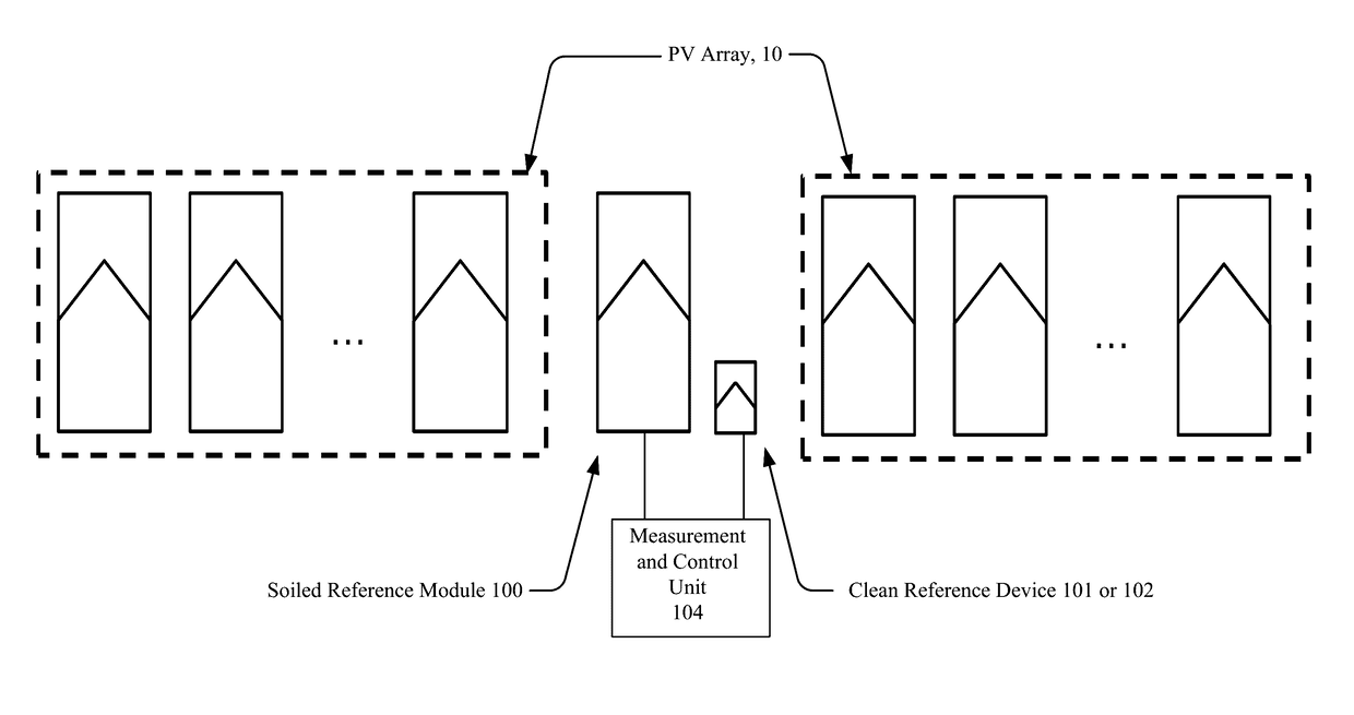
[0037]The disclosed subject matter provides a system for measuring the fraction of power lost due to PV module soiling in an actual solar power plant or a prospective solar power plant to be constructed at or near the site of the measuring system.

[0038]Although described with particular reference to a soiling measurement system for solar power plants, those with skill in the arts will recognize that the disclosed embodiments have relevance to a wide variety of areas in addition to those specific examples described below.

[0039]All references, including publications, patent applications, and patents, cited herein are hereby incorporated by reference to the same extent as if each reference were individually and specifically indicated to be incorporated by reference and were set forth in its entirety herein. Provided, however, to the extent there exists a conflict between this disclosure and anything incorporated by reference, this disclosure shall supersede.

Non-Uniform Soiling

[0040]PV ...


PUM


Abstract

A system for measuring the power or energy loss in a photovoltaic array due to soiling, which is the accumulation of dust, dirt, and / or other contaminants on the surfaces of photovoltaic modules, comprising: a pair of photovoltaic reference devices placed within or near the photovoltaic array and co-planar to the modules comprising the array, wherein one reference device is a module similar to those of the array and is allowed to accumulate soiling at the natural rate, and wherein the second reference device is a module or a cell and is periodically cleaned; and a measurement and control unit which measures and compares the electrical outputs of the soiled reference device and the clean reference device in order to determine the fraction of power lost by the soiled reference module due to soiling.

Description

CROSS-REFERENCE TO RELATED APPLICATIONS[0001]This application is a continuation-in-part (CIP) of U.S. Non-Provisional patent application Ser. No. 14 / 381,165, filed Aug. 26, 2014, and claims the benefit thereof, wherein U.S. Non-Provisional patent application Ser. No. 14 / 381,165 claims priority to U.S. Provisional Patent Application Ser. No. 61 / 876,134, filed Sep. 10, 2013, and to PCT Patent Application Ser. No. PCT / US13 / 71315. Each of the above are incorporated herein by reference.FIELD OF THE INVENTION[0002]The invention relates to a system for measuring power or energy loss in solar power plants due to accumulation of dust, dirt, and other contaminants (or “soiling”) on photovoltaic (PV) modules.BACKGROUND OF THE INVENTION[0003]Arrays of photovoltaic (PV) modules, also known as solar panels, are used in solar power installations for converting sunlight to electricity. Such installations range from small rooftop systems on residential or commercial buildings to large utility-scale ...

Claims


Application Information

Patent Timeline
IPC IPC(8): H02S50/10H02S40/10
CPCH02S40/10H02S50/10H02S50/00Y02E10/50
Inventor GOSTEIN, MICHAEL
Owner ATONOMETRICS
Learn More