
Method and system for emitter identification using transmission signatures

Inactive Publication Date: 2006-02-21
AGILENT TECH INC
View PDF12 Cites 38 Cited by
  • Summary
  • Abstract
  • Description
  • Claims
  • Application Information

AI Technical Summary

Benefits of technology

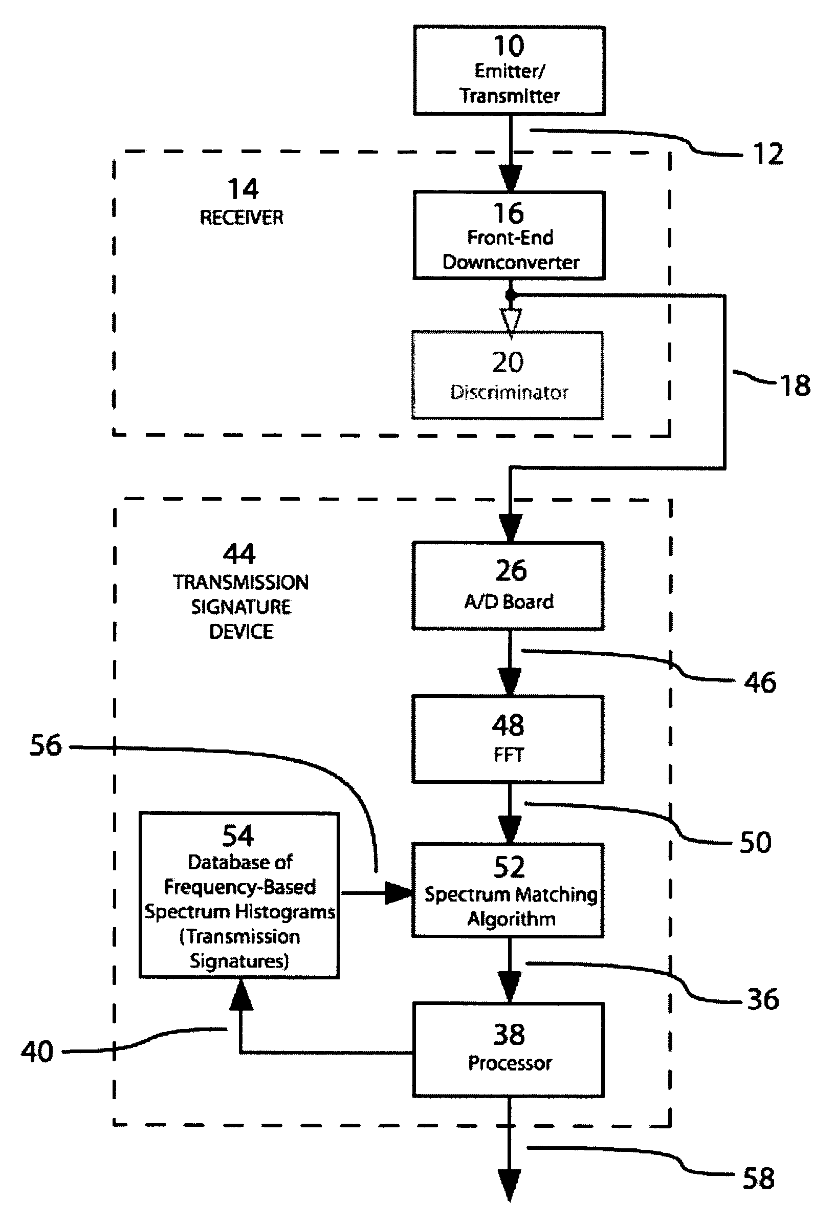
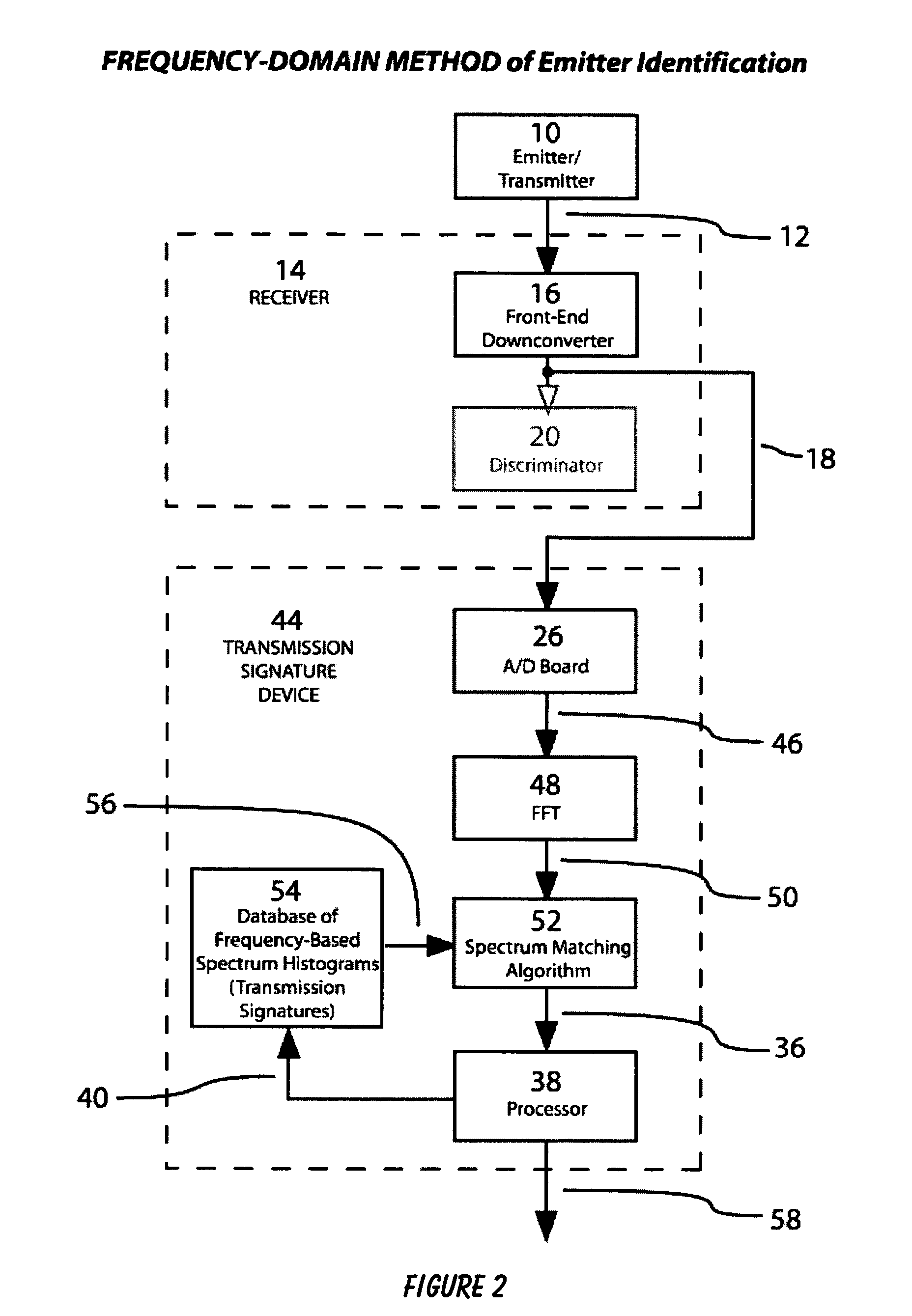
[0010]In light of the aforementioned problems associated with the prior method and systems, it is an object of the present invention to provide a Method and System for Emitter Identification Using Transmission Signatures. The preferred system should be able to take in the undemodulated IF of the receiver and perform identification algorithms on that data. Such a frequency-based technique from the undemodulated IF is inherently more accurate due to the fact that there is unfiltered information that can be characterized and used for identification purposes that is not available in the prior art method. Furthermore, the preferred system must be able to perform these functions in real-time and present the operator with an intelligent evaluation as to the identification of an emitter, or the presence of a new emitter. It is a further object that this system is capable of being fully automated which would reduce the processing time to react to the results of the emitter identification. It is still even further an object that an alternative embodiment of the present invention is to feasibly remote control the emitter identification system over a network and collect the same information from similar systems. In this way, a far more efficient System can be achieved in which emitters can be determined, tracked, or monitored more quickly from a centralized command facility.

Problems solved by technology

These methods are not extremely accurate and have certain limitations.

Method used


Image

  • Method and system for emitter identification using transmission signatures
  • Method and system for emitter identification using transmission signatures
  • Method and system for emitter identification using transmission signatures

Examples


Embodiment Construction

[0016]The following description is provided to enable any person skilled in the art to make and use the invention and sets forth the best modes contemplated by the inventor of carrying out his invention. Various modifications, however, will remain readily apparent to those skilled in the art, since the generic principles of the present invention have been defined herein specifically to provide a Method and System for Emitter Identification Using Transmission Signatures.

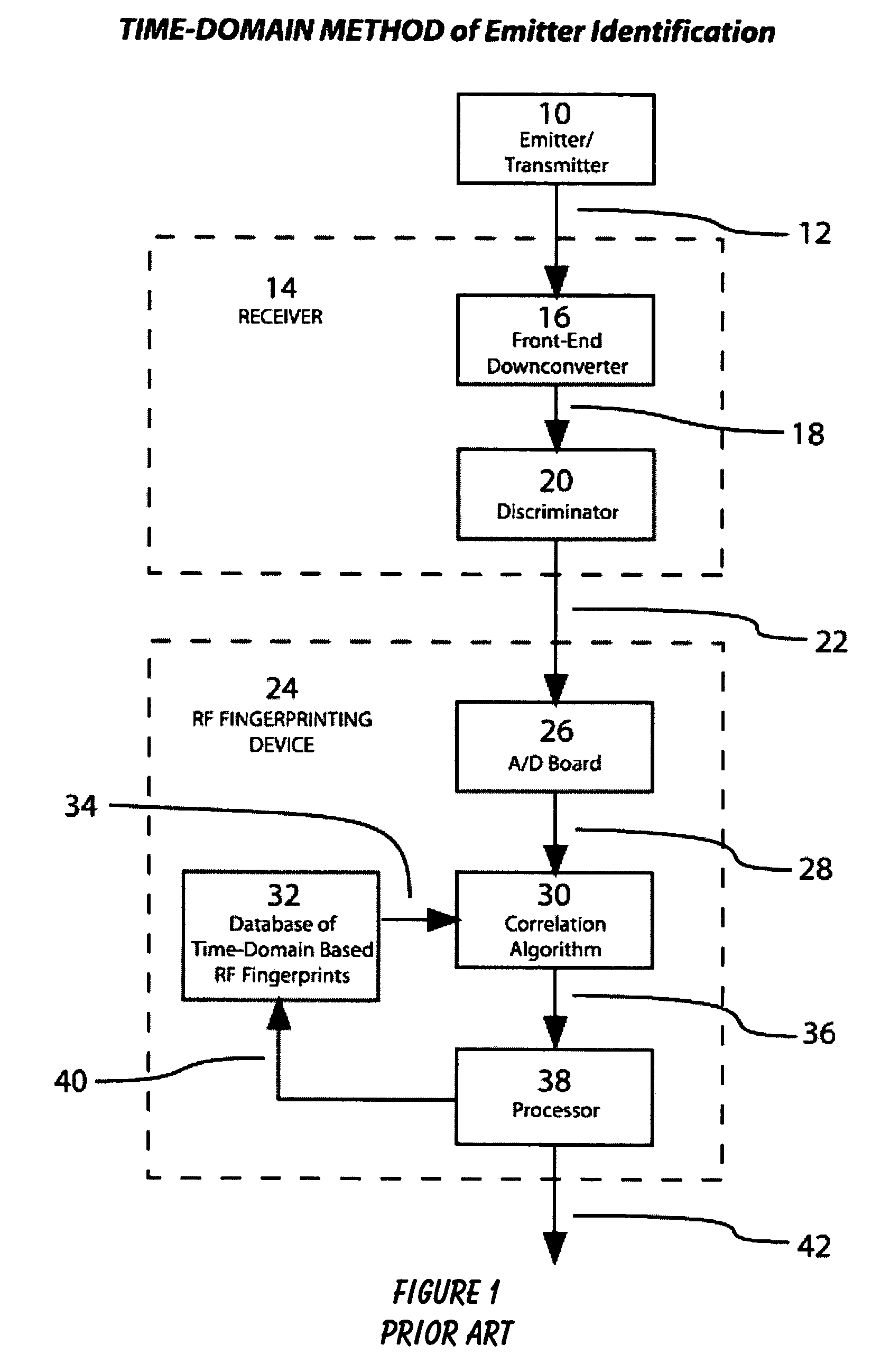
[0017]The present invention can best be understood by initial consideration of FIG. 1. FIG. 1 is a drawing of the prior art method of emitter identification that utilizes a time-domain based analysis of an emitter's output signals. The technique of radio fingerprinting was developed in the 1940's and 1950's and has not undergone significant improvement over the years. There have been varying applications for the technique, but the fundamental concept of how radio fingerprinting works has not itself changed.

[0018]This ...


PUM


Abstract

A Method and System for Emitter Identification Using Transmission Signatures is disclosed. Also disclosed is a system that is able to take in the undemodulated IF of the receiver and perform identification algorithms on that data. The system is further able to perform these functions in real-time and present the operator with an intelligent evaluation as to the identification of an emitter, or the presence of a new emitter. Still further, the system is capable of being fully automated to reduce the processing time to react to the results of the emitter identification. Furthermore, the present invention can feasibly remotely control the emitter identification system over a network and collect the same information from similar systems. In this way, a far more efficient System can be achieved wherein emitters can be determined, tracked, or monitored more quickly from a centralized command facility.

Description

[0001]This application is filed within one year of, and claims priority to Provisional Application Ser. No. 60 / 449,313, filed Feb. 24, 2003.BACKGROUND OF THE INVENTION[0002]1. Field of the Invention[0003]This invention relates generally to Electronic Transmission Systems and, more specifically, to a Method and System for Emitter Identification Using Transmission Signatures.[0004]2. Description of Related Art[0005]Wireless communications involves the use of emitters (transmitters, transceivers, etc.) to transmit their signals electromagnetically. From a signal intelligence point of view, there are obvious advantages in being able to uniquely identify one emitter from the next. In the past, the methods that were employed to do this would identify each emitter by observing certain output signal characteristics. Prior art methods utilized time-domain based observations, or “RF fingerprints”, to differentiate one emitter from the next. These methods are not extremely accurate and have ce...

Claims


Application Information

Patent Timeline
IPC IPC(8): G01S7/292H04B17/40
CPCH04W99/00H04W24/00
Inventor KARLSSON, LARS
Owner AGILENT TECH INC
Learn More