Desalination method and system using a continuous helical slush removal system

a technology of helical slush removal and desalination method, which is applied in the direction of crystallization separation, water treatment parameter control, separation process, etc., can solve the problems of insufficient drinking water to support, inconvenience or cost prohibitive, etc., and achieve the effect of reducing the temperature of seawater and facilitating the continuous removal of ice crystals

Active Publication Date: 2010-01-28
ENIS BEN M +1
View PDF39 Cites 24 Cited by
  • Summary
  • Abstract
  • Description
  • Claims
  • Application Information

AI Technical Summary

Benefits of technology

[0008]The present invention facilitates the continuous removal of ice crystals in conjunction with the use of a desalination system that uses a compressed air energy system to freeze the seawater and form a slushy ice / brine mixture at the bottom of a crystallization chamber. Preferably, the desalination system incorporates a compressed air energy system, wherein compressed air is released to produce chilled air as a by-product, which can then be introduced into the crystallization chamber, and used to flash freeze seawater droplets that are sprayed into the crystallization chamber. Rather than using a refrigerant to reduce the temperature of the seawater for desalination purposes, as in the case of past freeze crystallization methods, the present invention preferably uses clean chilled air, derived from releasing and expanding compressed air energy, directly mixed with the seawater droplets, to produce frozen ice particles to desalinate seawater.

Problems solved by technology

Nevertheless, there are many geographical areas throughout the country and world where fresh drinking water is not readily available, or where it might be inconvenient or cost prohibitive to transport the water to where it is needed.
There are also large population centers near the coastline, such as in dry or arid climates, where there is sufficient seawater, but not enough drinking water available to support the population.

Method used


Image

  • Desalination method and system using a continuous helical slush removal system
  • Desalination method and system using a continuous helical slush removal system
  • Desalination method and system using a continuous helical slush removal system

Examples


Embodiment Construction

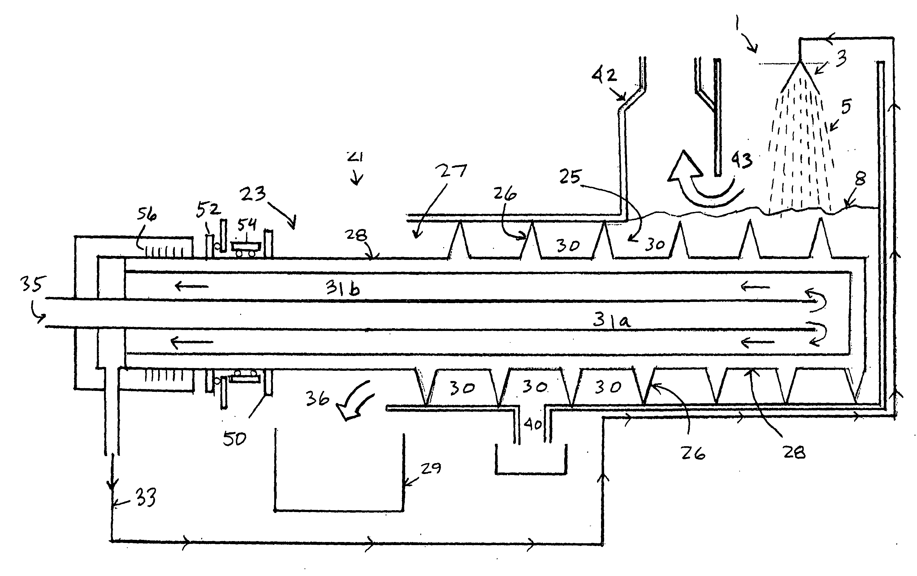
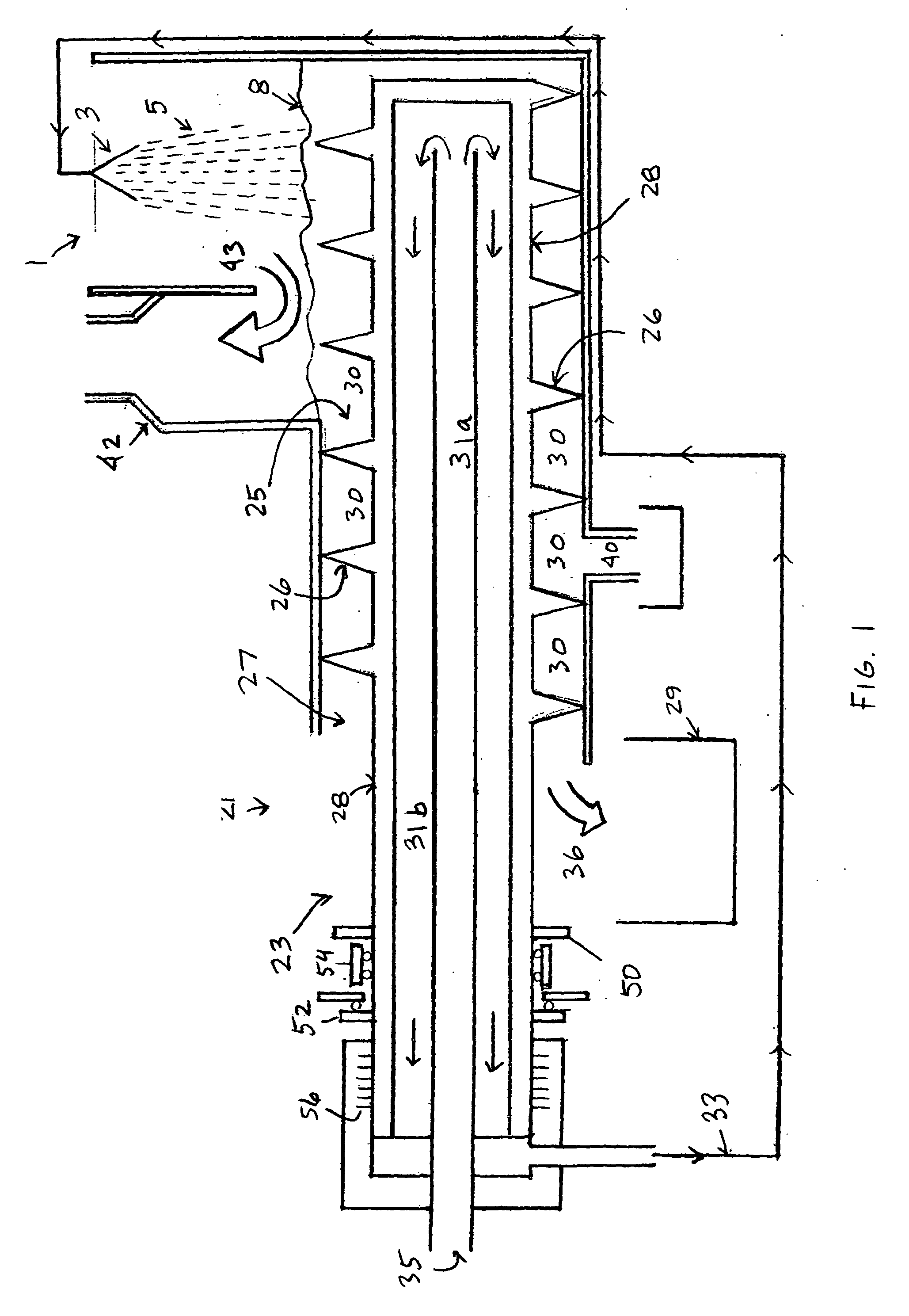
[0031]As shown in FIG. 1, the desalination system of the present invention preferably comprises an insulated crystallization mixing chamber 1, wherein seawater and chilled air can be intermixed therein. This chamber 1 and side chamber 42 are not shown to scale in FIG. 1. The lower section of chamber 1, which comprises the slush removal system of the present invention, will be discussed in more detail below.

[0032]At the top of chamber 1, there is preferably a nozzle or an array of nozzles 3 that can form a spray of seawater droplets 5 into chamber 1. The nozzle 3 preferably produces a volumetric flow of seawater which can be sprayed as a droplet cloud 5 into chamber 1, as shown. The desalination system preferably pressurizes and filters the seawater before it is passed through nozzle 3 into chamber 1.

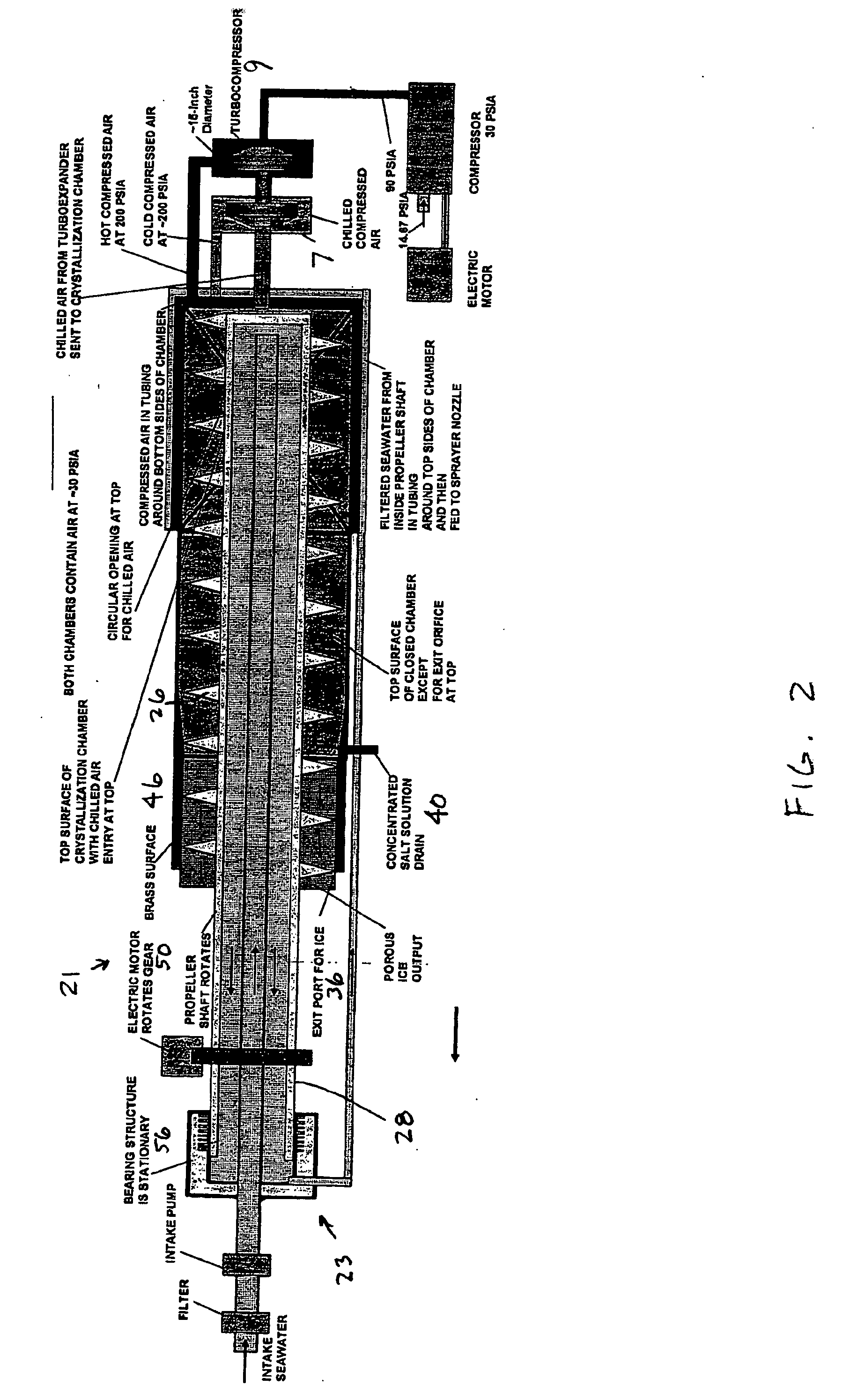
[0033]The preferred embodiment uses a compressed air energy system to produce chilled air which is introduced into chamber 1 and used to flash freeze the droplets 5. The chilled air is p...


PUM

PropertyMeasurementUnit
pressureaaaaaaaaaa
freezing pointaaaaaaaaaa

Abstract

The invention relates to a desalination method and system that uses freeze crystallization technology that incorporates the use of compressed air energy as the source for freezing temperatures. When compressed air is released by a turbo expander, chilled air is produced as a by-product, wherein the chilled air is introduced into a chamber, wherein a spray cloud of seawater droplets, which has been pre-chilled by heat exchange with the cold chamber walls, is then circulated and exposed to the chilled air in the chamber. The droplets then settle at the bottom of the chamber, wherein they are deposited at slightly above the eutectic temperature, to form an ice / brine slush mixture. A slush removal mechanism with a screw-like helical blade is provided to continuously remove the ice particles from the chamber.

Description

FIELD OF THE INVENTION [0001]The present invention relates to the field of desalination systems, and in particular, to a desalination method and system that uses a compressed air energy system to produce an ice / brine mixture at the bottom of a crystallization chamber, wherein a helical slush removal system is provided to enable the ice particles to be removed from the chamber on a continuous basis.BACKGROUND OF THE INVENTION [0002]In the United States, there is typically an adequate supply of fresh drinking water available in most regions of the country. Even in areas where water supplies are scarce, efforts have been made to transport water from where it is available, to where it is needed. For example, a significant amount of water is currently being transported from the Colorado River, via the California Aqueduct, to heavily populated, but dry, regions of Southern California, so that sufficient water will be available, not only for drinking purposes, but for agriculture and irrig...

Claims


Application Information

Patent Timeline
Patent Type & Authority Applications(United States)
IPC IPC(8): C02F1/22C02F1/02B01D9/00
CPCC02F1/10C02F1/12C02F1/22C02F2303/26C02F2209/02C02F2209/03C02F2303/16C02F2103/08Y02W10/37Y02A20/124
Inventor ENIS, BEN M.LIEBERMAN, PAUL
Owner ENIS BEN M
Why Eureka
Try Eureka