
Fan clutch

a fan clutch and fan body technology, applied in the direction of fluid couplings, liquid fuel engines, couplings, etc., can solve the problems of increasing production costs, requiring a great deal of disassembly and disassembly of the fan clutch, and substantially more difficult to replace the v-belt, so as to simplify the connection

Active Publication Date: 2010-01-28
MAHLE INT GMBH
View PDF10 Cites 9 Cited by
  • Summary
  • Abstract
  • Description
  • Claims
  • Application Information

AI Technical Summary

Benefits of technology

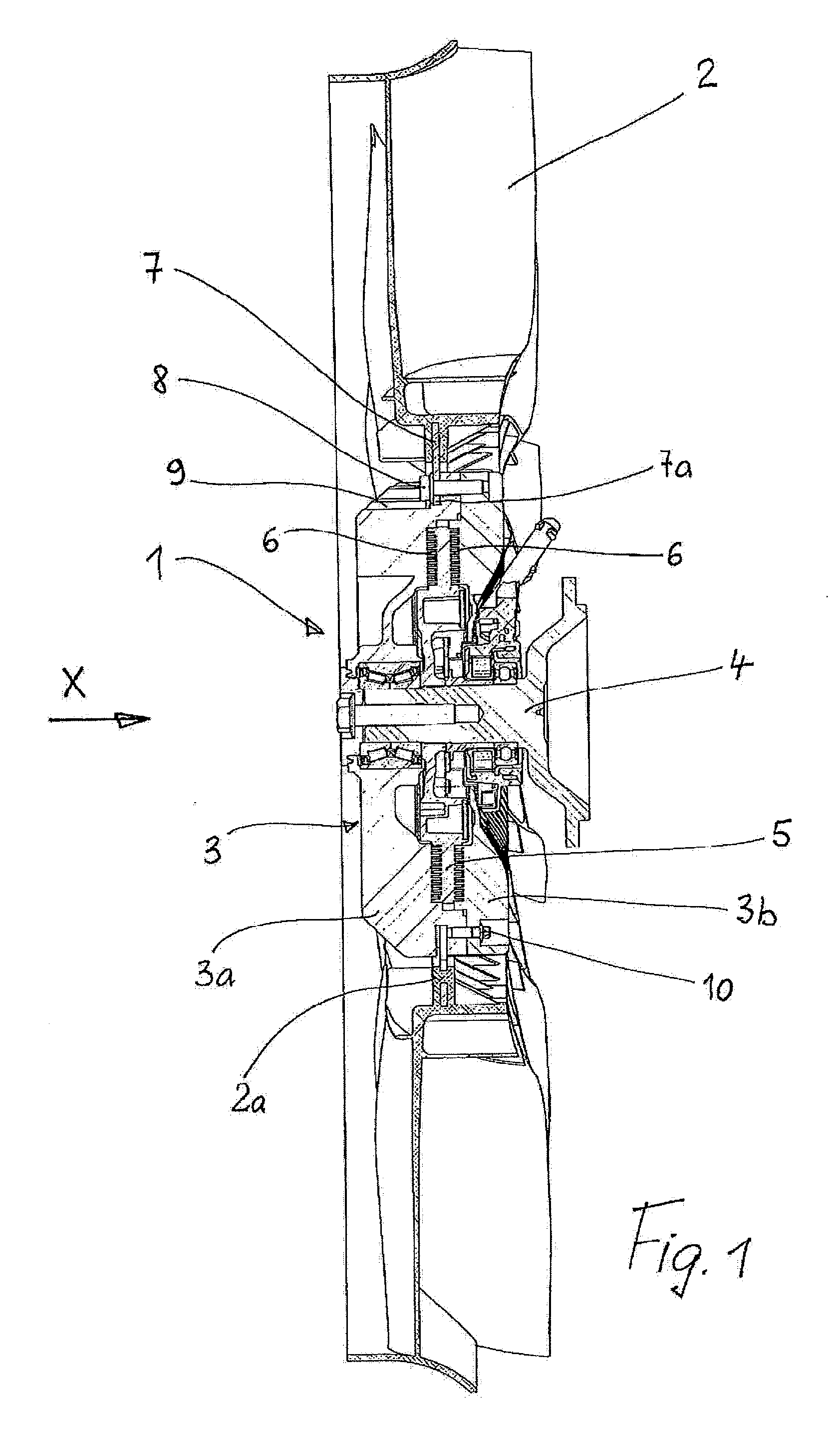
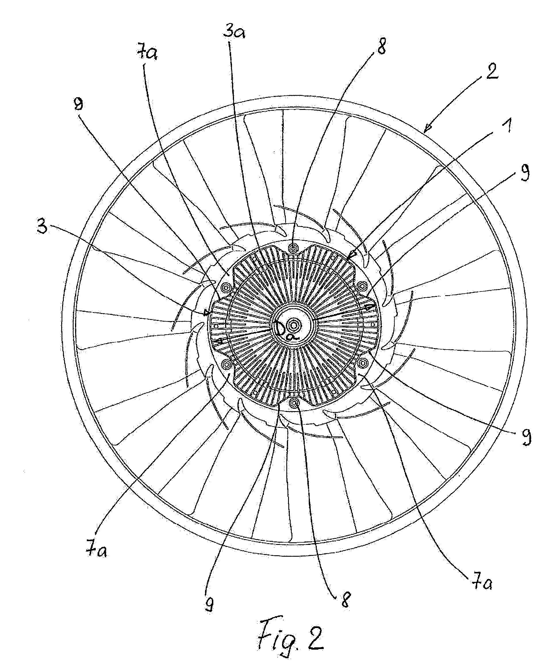
[0010]According to an embodiment of the invention, it is provided that attachment niches, with which attachment tabs extending inward from the fan flange ring engage, are situated on the front and the back of the fan clutch. The attachment niches on the front are offset in relation to the attachment niches on the back in the circumferential direction, i.e., they are situated in a “staggered” manner. This achieves the advantage that the fan may be mounted and attached to the same clutch from either the front or the back. The mounting and fastening directions are therefore preferably the same.
[0012]According to a further embodiment, the attachment screws for attaching the flange ring to the clutch housing may simultaneously form the connecting elements for connecting the two housing parts. This simplifies construction and reduces the number of components.
[0013]According to yet a further embodiment, a gap which runs in the circumferential direction and can be preferably dimensioned to be larger than the wall thickness of the flange ring, can be provided between the front and back attachment niches. This achieves the advantage that the fan may be mounted, for example from the front, subsequently rotated in the circumferential direction and removed again via the back attachment niches or attached from the back. The same is possible in the opposite direction, i.e. from the back to the front. The fan may thus be “screwed on” more or less in the axial direction via the clutch or, in other words, inserted in the manner of a quarter-turn fastener. This is advantageous, in particular, for disassembly in the event of maintenance or repair work. This is also advantageous for mounting the fan, in particular in the case of heavy units, since it enables the clutch to be mounted first and the fan to be attached to the clutch. The flexibility of the fan clutch is substantially improved thereby. At the same time, the unit costs are reduced, due to the use of standard tools for different types of attachment.
[0014]According to a further embodiment, the fan clutch can be designed as a fluid friction clutch which can include two housing parts, a drive wheel having a drive shaft and a working space in which a torque is transmittable by fluid friction. Fluid friction clutches of this type have proven to be particularly sturdy and reliable for driving a fan in motor vehicles.

Problems solved by technology

This can require different housings, i.e. different diecasting moulds—in part for the same clutch—which increases the production costs.
A further disadvantage is the fact that the fan clutch, i.e. the clutch and the fan, requires a great deal of effort to be disassembled if any maintenance and repair work is to be done.
For example, this makes it substantially more difficult to replace a V-belt, which is situated between the fan and the engine and is used to drive auxiliary units.

Method used


Image

  • Fan clutch
  • Fan clutch
  • Fan clutch

Examples


Embodiment Construction

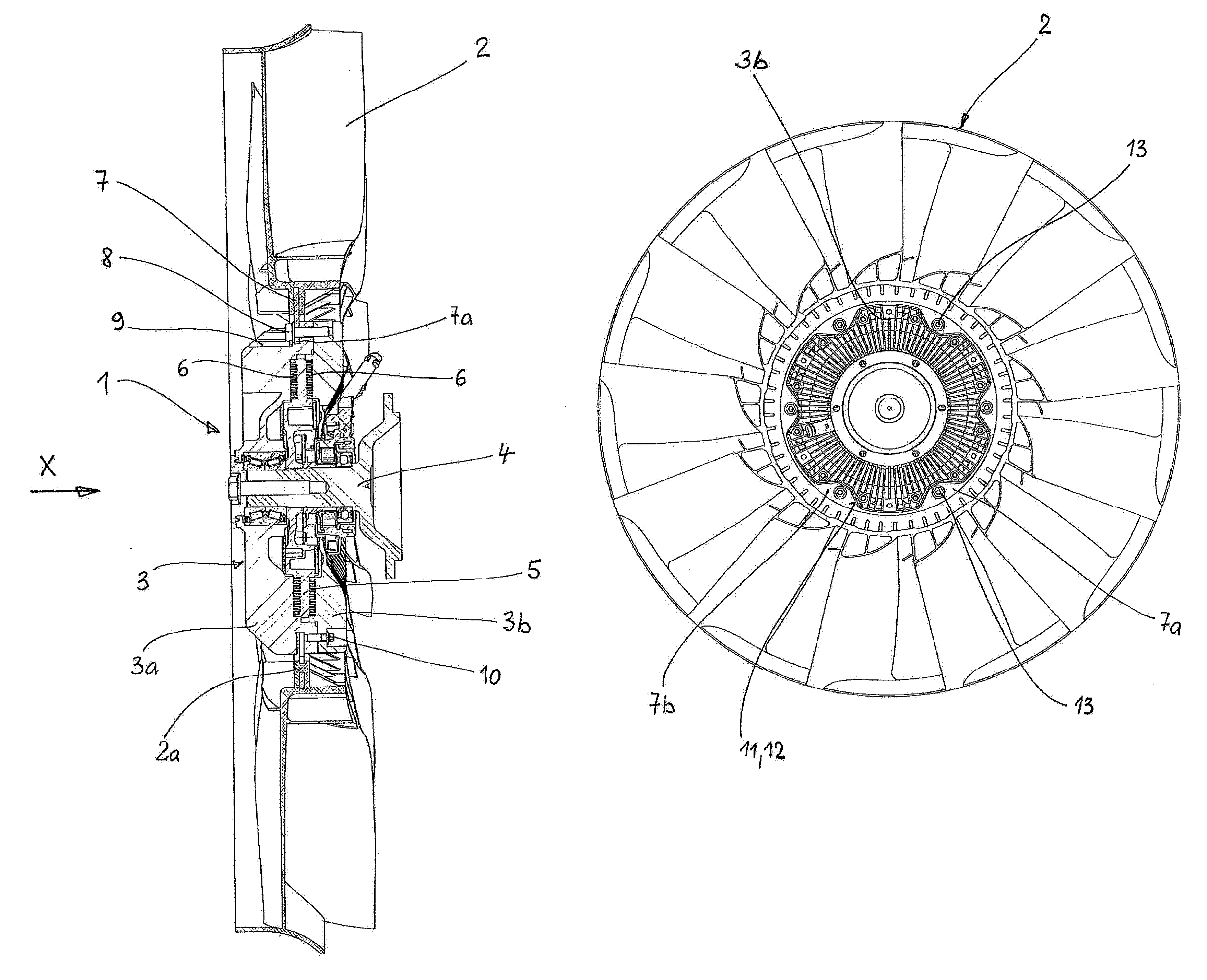
[0022]FIG. 1 shows a fan clutch designed as a fluid friction clutch 1, to which a fan 2 designed as an axial fan, a so-called ring fan, is attached on the front of fan clutch 1, hereinafter referred to in short as clutch 1. Fan 2 and clutch 1 are part of a cooling system (which is not illustrated) for the internal combustion engine of a motor vehicle. Clutch 1 has a housing 3, which includes a first, front-facing housing part 3a, also referred to as front housing part 3a, and a second, rear or back housing part 3b. Front housing part 3a is mounted on a drive shaft 4, which is driven by the engine (not illustrated) of the motor vehicle, e.g. by the crankshaft thereof. A drive wheel 5, which together with the two housing parts 3a, 3b forms a working chamber 6 for transmitting a torque from drive shaft 4 to clutch housing 3 and thus to fan 2, is non-rotationally connected to drive shaft 4. For information of the functions of a fluid friction clutch and the regulation thereof, reference...


PUM


Abstract

A fan clutch is provided to which a fan may be removably attached with the aid of a flange ring, the fan clutch having a housing that comprises a first front housing part and a second rear housing part to which the flange ring is attachable with the aid of connecting elements (8). The housing has circumferential attachment niches which are situated in an offset manner in the circumferential direction on both the front and the back of the housing and into which attachment tabs situated on the flange ring are insertable either from the from of the fan clutch or from the rear thereof.

Description

[0001]This nonprovisional application claims priority under 35 U.S.C. § 119(a) to German Patent Application No. 10 2008 035 185.7, which was filed in Germany on Jul. 28, 2008, and which is herein incorporated by reference.BACKGROUND OF THE INVENTION[0002]1. Field of the Invention[0003]The invention relates to a fan clutch.[0004]2. Related Art[0005]A fan clutch is known from DE 103 38 432 A1, which is incorporated herein by reference, and which is designed as a fluid friction clutch, is used in a cooling system of a motor vehicle. The fan clutch is driven by the motor vehicle engine and drives a fan attached to the clutch housing as a function of the cooling requirements of the cooling system. This attachment is via a flange ring which, on the one hand, is embedded into the fan hub and, on the other hand, is attached to the clutch housing in a manner that allows it to be removed, in particular with the aid of screws. The attachment is either on the back of the clutch (FIG. 1 of DE 10...

Claims


Application Information

Patent Timeline
Patent Type & Authority Applications(United States)
IPC IPC(8): F16D31/00
CPCF04D29/329F04D25/02
Inventor SCHULTHEISS, GEROLDANGERMAIER, JOERGSIXT, EBERHARDSETZER, SVEN
Owner MAHLE INT GMBH
Learn More