Method and Device for Transmission Noise Suppression

Active Publication Date: 2010-01-28
AUDI AG
View PDF7 Cites 7 Cited by
  • Summary
  • Abstract
  • Description
  • Claims
  • Application Information

AI Technical Summary

Benefits of technology

[0004]According to the invention, it is proposed that under defined operating conditions of the transmission, the throughput amount of oil is increased in such a way that a defined drag torque occurs at the multi-disk clutch that is opened. Consequently, the clutch control is not used, but rather the throughput amount of cooling oil is correspondingly increased. In this case, the oil within the air gap of the multi-disk clutch, similar to a visco clutch, produces an increasing torque, which is sufficient to damp the tooth flank play or to eliminate rattling or transmission noises. In this case, no additional wear occurs at the respective multi-disk clutch.
[0008]The throughput amount of oil can preferably be controlled via a timed control valve and thus makes it possible, e.g., to increase the throughput amount only to the extent that is exactly necessary for suppressing the temporarily prevailing transmission noise.
[0011]In addition to or as an alternative to the above embodiment, the rattle or transmission noises can be eliminated by activating a synchronizer clutch, which can be engaged in a known way to switch gears with loose gears. Activating the synchronizer clutch accordingly provides a desynchronization of the selector gears, preferably most inclined to rattle.
[0013]In another embodiment, the rattle or transmission noise can be avoided by a corresponding activation of the clutch of a preselected gear. In this case, the clutch can be applied so that the rattle is stopped. The activation or adjusting of the clutch can be carried out based on the gear, the speed, the torque, or the oil temperature. The adjustment of the clutch is carried out by means of an acoustic or rattle sensor, or the like.
[0014]The clutch can be applied temporarily and / or based on assessment of the accompanying deterioration of efficiency. In addition, the degree of the application of the clutch can be adapted to the specific motor vehicle or use or can be adjusted to what is comfortable. Optionally, based on the invention, a two-mass flywheel can be omitted, thereby saving weight, installation space, or cost.

Problems solved by technology

Activating the multi-disk clutch, which is opened in each case, into the skid state, however, unavoidably produces elevated clutch wear.

Method used


Image

  • Method and Device for Transmission Noise Suppression
  • Method and Device for Transmission Noise Suppression

Examples


Embodiment Construction

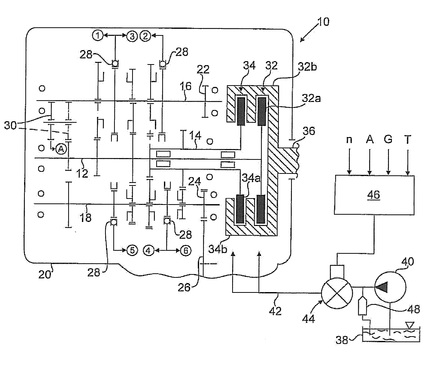
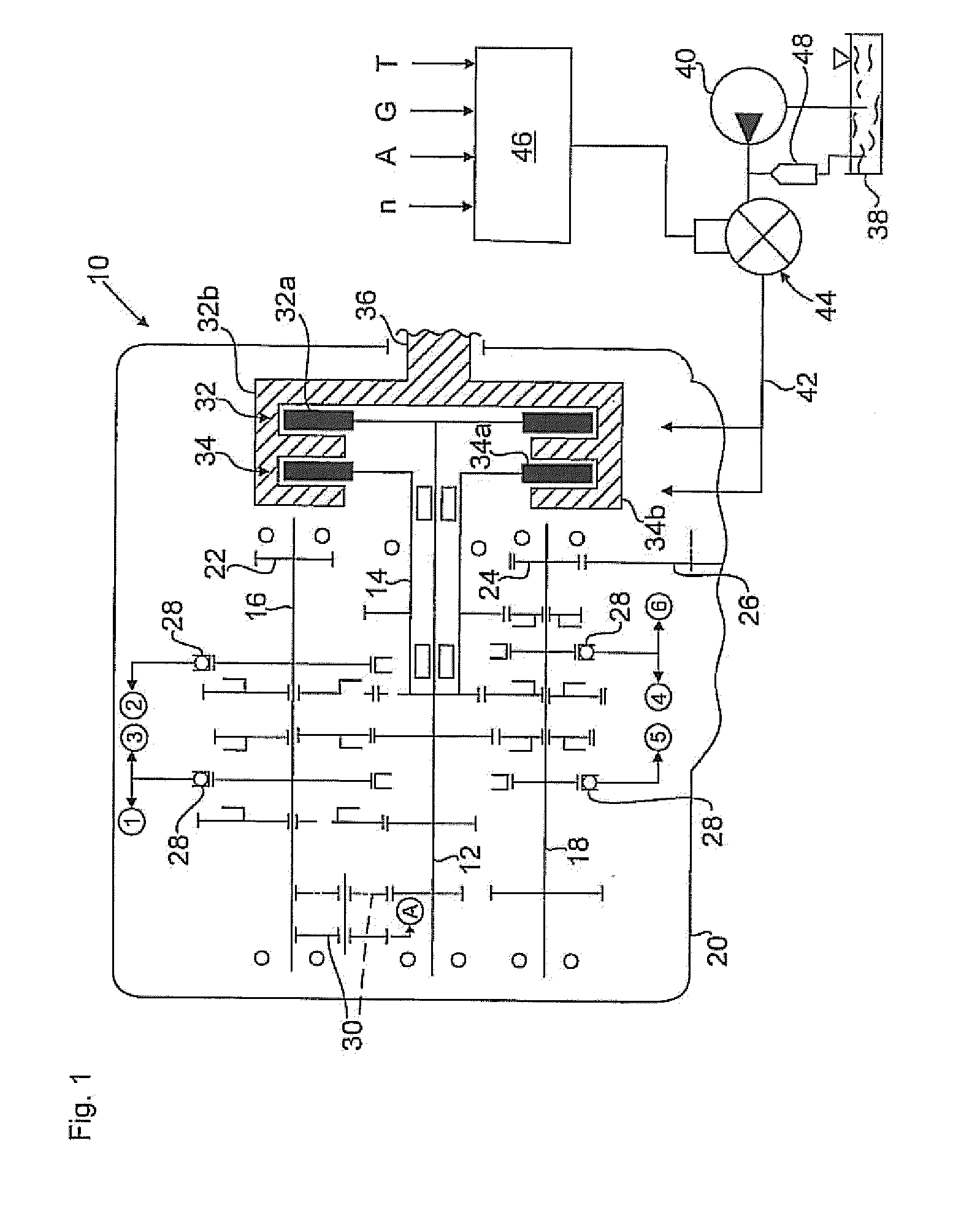
[0016]In the drawing, a double-clutch gear for motor vehicles, which is essentially composed of two input shafts 12, 14 and two output shafts 16, 18, which are mounted to rotate in a gearbox 20, is designated as 10. As is evident, the input shaft 14 is a hollow shaft that is mounted to rotate on the input shaft 12. The two output shafts 16, 18 mesh via stationary gears 22, 24 with a gear 26 of a differential gear, not shown.

[0017]Between the input shafts 12, 14 and the output shafts 16, 18, undesignated stationary gears and loose gears that can be switched by synchronizer clutches 28, which define the gears 1 to 6 and a reverse gear R in the activated state, are provided conventionally. For the reverse gear R, a corresponding reversing gear 30 is provided conventionally.

[0018]The two input shafts 12, 14 of the transmission 10 can be coupled via wet-running multi-disk clutches 32, 34 in an alternating way with the driving internal combustion engine or its crankshaft 36 (only indicate...


PUM


Abstract

The invention relates to a method and a device for suppressing transmission noise from automatic transmissions, in particular for motor vehicles, the transmission having at least two alternating multi-disk clutches that control a power flow via a gearing mechanism through which oil flows to cool the clutches and to reduce wear and tear on them. To create a method and a device that are of simple design and that can operate without wear and tear, it is proposed that under defined operating conditions of the transmission, the throughput amount of oil is increased in such a way that a defined drag torque occurs at the multi-disk clutch that is opened.

Description

[0001]The invention relates to a method and a device for the suppression of transmission noise from automatic transmissions, in particular in motor vehicles.BACKGROUND OF THE INVENTION[0002]Such a method is described in EP 1 617 108 B1, which proposes activating one of the two multi-disk clutches that control the drive flows in a state of skidding in which it transfers a drag torque to suppress transmission noise or gear rattle. It is thus achieved that in certain operating states of the transmission, gears that are idle or that are not transferring any load are damped, i.e., do not produce any tooth flank noise excited by torsional vibrations. Activating the multi-disk clutch, which is opened in each case, into the skid state, however, unavoidably produces elevated clutch wear.[0003]The object of the invention is to propose a method of the generic type that can be implemented with relatively simple means and does not cause any elevated clutch wear. Furthermore, an advantageous devi...

Claims


Application Information

Patent Timeline
IPC IPC(8): F16H57/04F16H37/06F16D23/00
CPCF16H61/688F16H57/0006
Inventor MAERKL, JOHANNSCHMIDT, ALEXANDER
Owner AUDI AG
Why Eureka
Try Eureka