Movable body apparatus, pattern forming apparatus and pattern forming method, device manufacturing method, manufacturing method of movable body apparatus, and movable body drive method

a technology of movable body and pattern forming, which is applied in the direction of photomechanical equipment, instruments, optics, etc., can solve the problems of increasing the size and weight of the entire apparatus. , to achieve the effect of improving the position controllability of objects, enhancing the downsizing of the entire movable body and enhancing the downsizing of the pattern forming apparatus

Active Publication Date: 2010-01-28
NIKON CORP
View PDF11 Cites 366 Cited by
  • Summary
  • Abstract
  • Description
  • Claims
  • Application Information

AI Technical Summary

Benefits of technology

[0015]With this apparatus, since the pattern forming apparatus is equipped with any one of the first to third movable body apparatus, position controllability of the object is improved according to the downsizing of the movable body, which makes it possible to perform high-precision pattern formation. Further, by the downsizing of the entire movable body apparatus, the downsi

Problems solved by technology

However, in the case of this type of stage device, as the substrate grows in size, the entire stage that holds the substrate also grows in size accordingly.
There is a risk that such increase in size of the substrate makes a stroke of the stage longer, which causes the entire apparatus to grow in size and weight.
Furthermore, when the stage grows in

Method used


Image

  • Movable body apparatus, pattern forming apparatus and pattern forming method, device manufacturing method, manufacturing method of movable body apparatus, and movable body drive method
  • Movable body apparatus, pattern forming apparatus and pattern forming method, device manufacturing method, manufacturing method of movable body apparatus, and movable body drive method
  • Movable body apparatus, pattern forming apparatus and pattern forming method, device manufacturing method, manufacturing method of movable body apparatus, and movable body drive method

Examples


Embodiment Construction

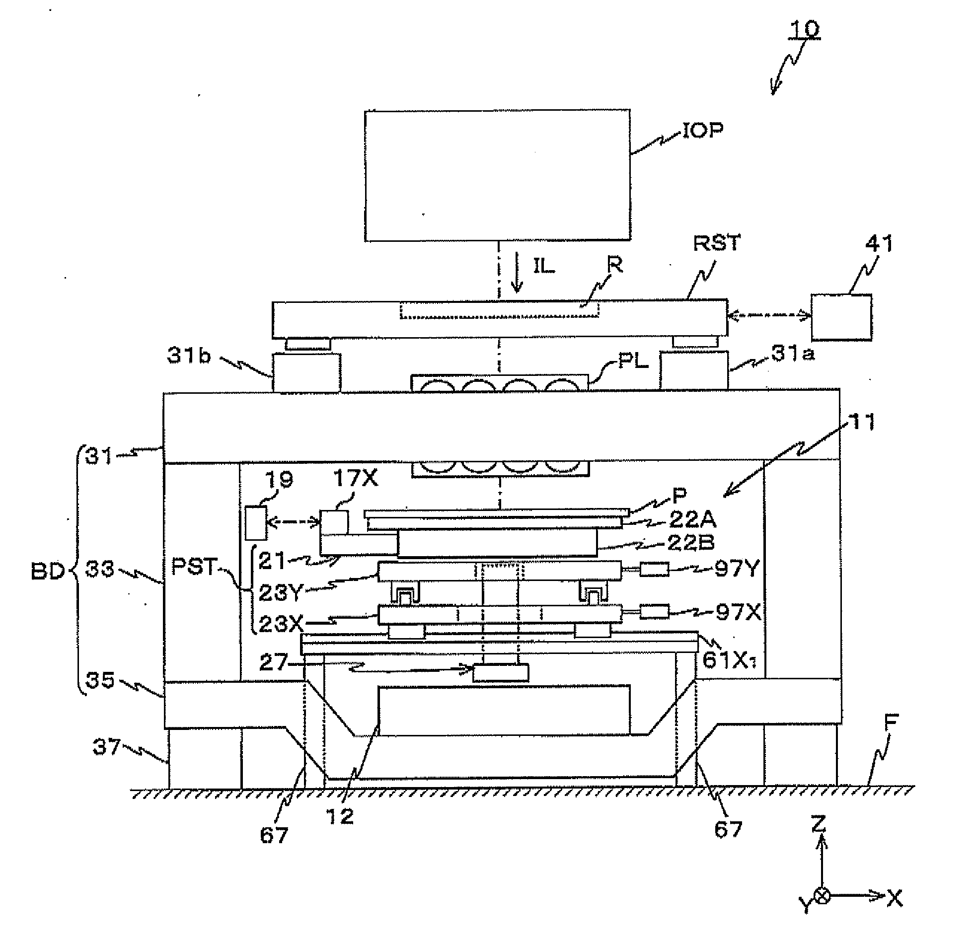
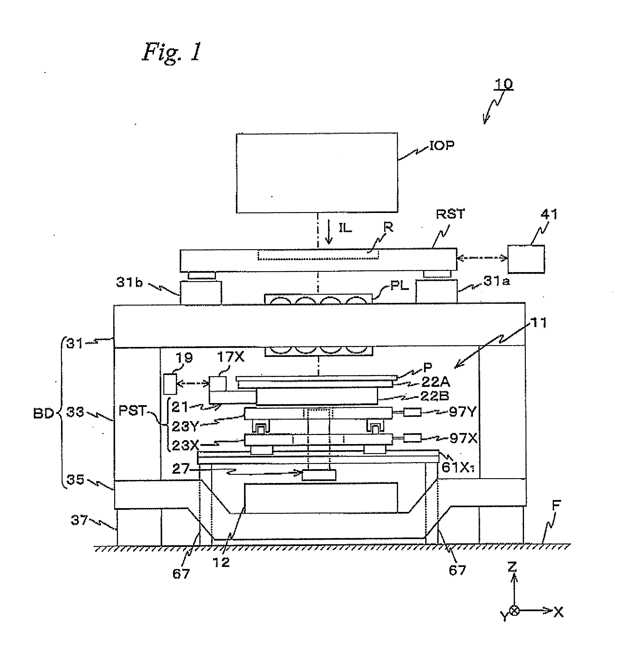
[0038]An embodiment of the present invention is described below, with reference to FIGS. 1 to 5B. FIG. 1 shows a schematic configuration of an exposure apparatus 10 related to the embodiment. Exposure apparatus 10 is a projection exposure apparatus by a step-and-scan method, that is, a so-called scanning stepper.

[0039]As shown in FIG. 1, exposure apparatus 10 includes an illumination system IOP, a reticle stage RST that holds a reticle R, a projection optical system PL, a stage device 11 that holds a substrate P so that substrate P is movable along an XY plane, a body BD on which reticle stage RST, projection optical system PL, stage device 11 and the like are mounted, and their control system, and the like.

[0040]Illumination system IOP is configured similar to the illumination system that is disclosed in, for example, Kokai (Japanese Patent Unexamined Application Publication) No. 2001-313250 (the corresponding U.S. Patent Application Publication No. 2003 / 0025890), Kokai (Japanese P...


PUM

PropertyMeasurementUnit
Angleaaaaaaaaaa
Weightaaaaaaaaaa
Pressureaaaaaaaaaa

Abstract

A substrate stage and an empty-weight canceling mechanism that supports an empty weight of the substrate stage are made up of separate bodies. Accordingly, the size and weight of the substrate stage (a structure including the substrate stage) can be reduced, compared with the case where the substrate stage and the empty-weight canceling mechanism are integrally configured. Further, due to movement of an X coarse movement stage and a Y coarse movement stage by an X drive mechanism and a Y drive mechanism, the substrate stage is driven in an XY plane and also the empty-weight canceling mechanism that supports the empty weight of the substrate stage is driven. With this operation, the substrate stage can be driven without difficulty even when the substrate stage and the empty-weight canceling mechanism are configured of separate bodies.

Description

CROSS-REFERENCE TO RELATED APPLICATIONS[0001]This application is a continuation of International Application PCT / JP2008 / 000437, with an international filing date of Mar. 4, 2008, the disclosure of which is hereby incorporated herein by reference in its entirety, which was not published in English.BACKGROUND OF THE INVENTION[0002]1. Field of the Invention[0003]The present invention relates to movable body apparatus, pattern forming apparatus and pattern forming methods, device manufacturing methods, manufacturing methods of movable body apparatus and movable body drive methods, and more particularly to a movable body apparatus equipped with a movable body that can move, a pattern forming apparatus to form a pattern on an object and a pattern forming method using the pattern forming apparatus, a device manufacturing method using the pattern forming method, a method of manufacturing the movable body apparatus, and a movable body drive method to drive the movable body.[0004]2. Descripti...

Claims


Application Information

Patent Timeline
IPC IPC(8): B44C1/22C23F1/08
CPCG03F7/70716H01L21/682G03F7/70791G03F7/70775H01L21/67706G03F7/70758
Inventor AOKI, YASUOSHIRASU, HIROSHIKUDO, YOSHIHIKO
Owner NIKON CORP
Why Eureka
Try Eureka