Detection Device Based on Surface Plasmon Resonance Effect

Inactive Publication Date: 2010-01-28
BIOSURFIT
View PDF57 Cites 17 Cited by
  • Summary
  • Abstract
  • Description
  • Claims
  • Application Information

AI Technical Summary

Benefits of technology

[0005]The SPR effect is an optical phenomenon that results from the local charge density oscillation in an interface between two media of differing dielectric properties. In particular, the SPR effect occurs at the interface between a dielectric medium and a metallic one (see reference 1). In this case, the surface plasmon wave is an electromagnetic wave with polarization TM (magnetic vector of the wave is perpendicular to the propagation direction and parallel to the interfacial plan). The SPR propagation constant β may be described by equation (1).
[0006]Where λ is the incident wavelength, ∈m is the dielectric constant of the metal (∈m=∈mr+i∈mi) and ∈d is the dielectric constant of the dielectric medium. The SPR only occurs if ∈mr<0 and |∈m|<∈d. In this case, the Surface Plasmon will propagate at the interface between the two media and will decrease exponentially from the interface to the bulk of each medium. On the other hand, the SPR effect is only detectable for metallic films with thicknesses in the range of tens to hundreds of nanometer In the case of a gold film, the SPR effect typically occurs with thicknesses between 25 nm and 150 nm).
[0007]Due to these facts and according to equation (1), the propagation constant β of the SPR is extremely sensitive to variations of the refractive index in the dielectric medium close to the interface. As a consequence, the SPR effect may be exploited for sensing applications, e.g. the immobilization of

Problems solved by technology

(a) the SPR detection principle based on the diffraction coupling, since this particular configuration presents several advantages when compared to the other possible SPR configurations. In particular, devices exploring the grating coupling configuration are much simpler and less expensive to produce when compared to the other SPR configurations. Moreover, the SPR detection based on the grating coupling may be further explored to achieve better performances then prism configurations. Although its analytical modeling presents additional complexity, the grating coupling enables the man of the art to play with parameters (not available in the prism configuration) adjustable to particular needs (e.g., by acting on the grating topography, conductive patterning, multilayer conductive / dielectric layering, etc. It is thus possible to build SPR sensors with properties unattainable in the prism configuration.
(b) the fluidic control system based on the centrifugal approach, and thus not requiring additional elements such has pumps, tubes and interconnects. This fact leads to low-cost, simple micro-fluidic systems of high performance and multiplexing capability.
(c) the substrate used for the detection integrating the different fluidic elements, such as reservoirs, inlets / outlets, channels, valves and at least one detection zones containing a detection surface built on a thin electrically conductive diffractive layer. This integration allows a great level of simplification of the fluidic substrate control, and consequently it allows for a great level of simplification in the final device use.

Method used


Image

  • Detection Device Based on Surface Plasmon Resonance Effect
  • Detection Device Based on Surface Plasmon Resonance Effect
  • Detection Device Based on Surface Plasmon Resonance Effect

Examples


first example

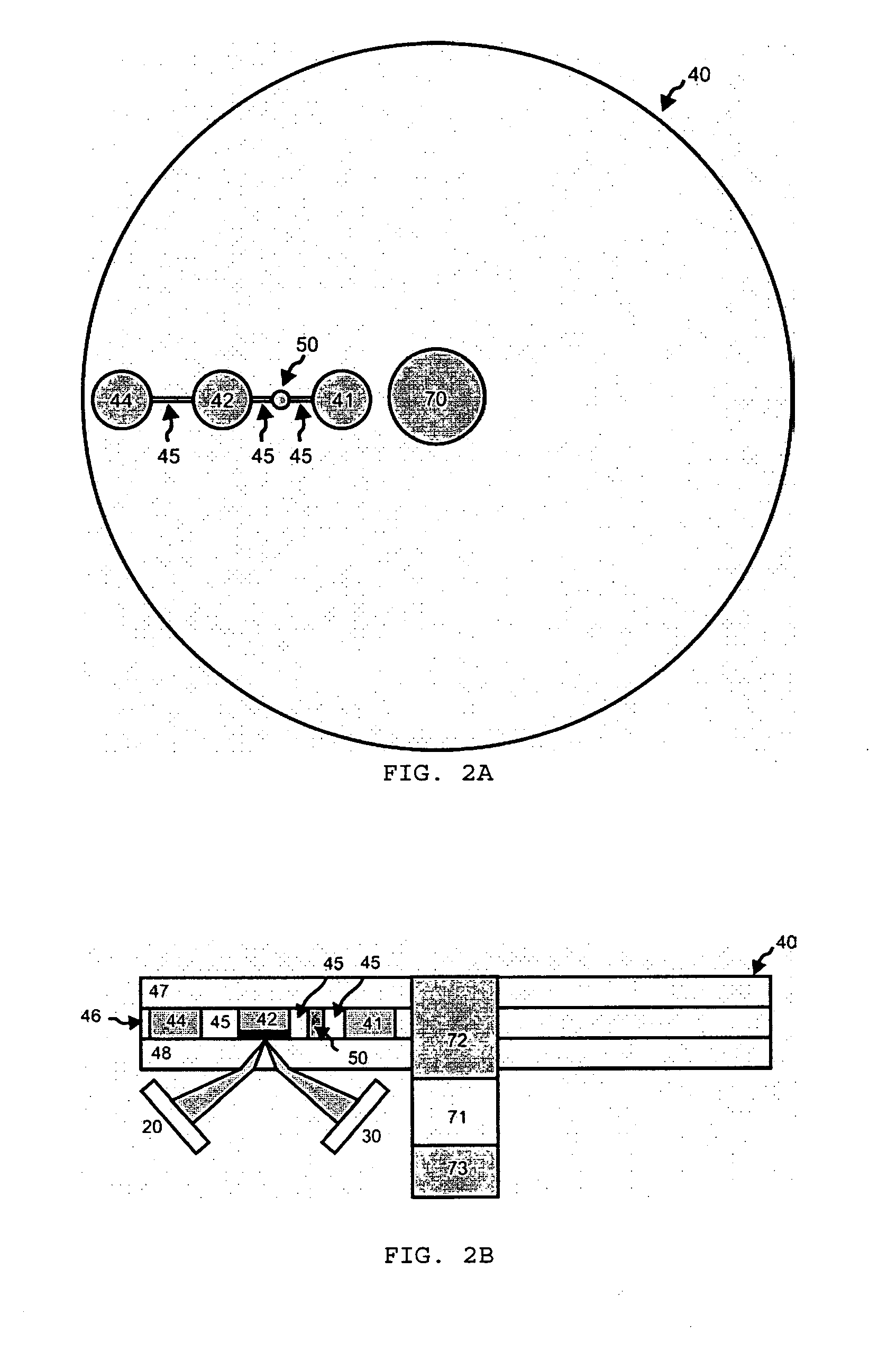
[0072]Let us consider as a first example the case where the sum of the total volumes for the channels 45, valve 50 and DZ 42 is smaller than the volume of initial reservoir 41. The initial reservoir 41, the valve 50, the DZ 42 and the final reservoir 44 are hydrophobic and the channels 45 are hydrophilic.

[0073]The system preferably operated in a regime with small angular accelerations. High angular accelerations may lead to disruption of the fluid column and this jeopardizes the desired flow behaviour and hence is considered an unfavourable scenario of the present invention.

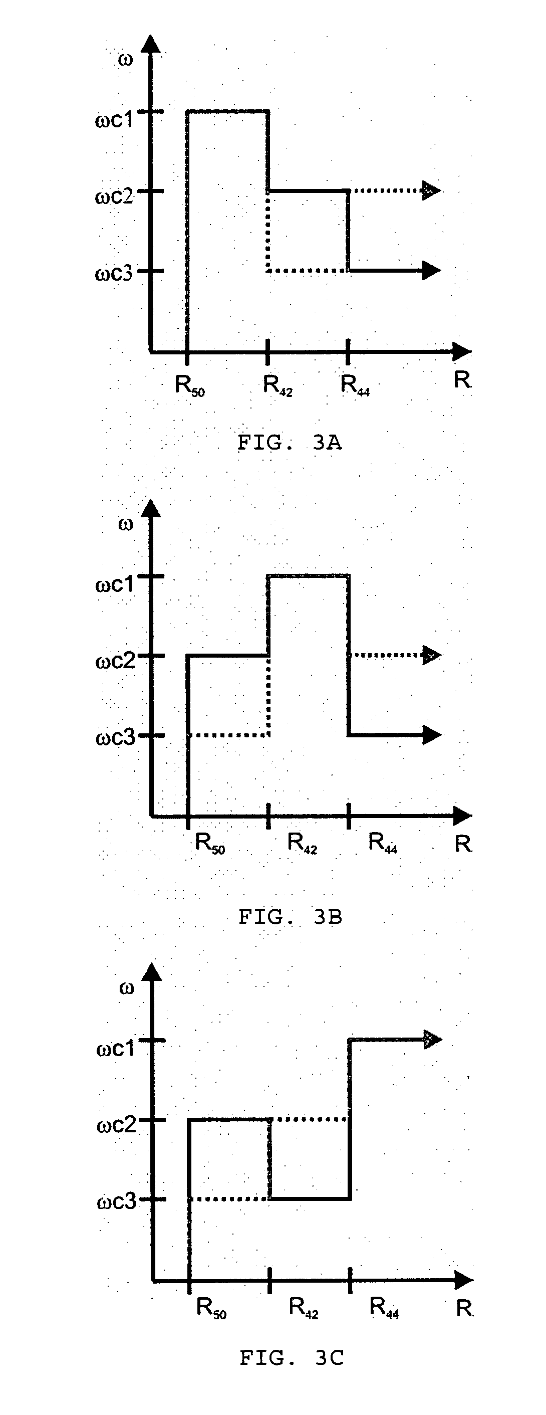
[0074]With the above-mentioned configuration, the system presents three barriers to the advancement of the fluid front (meniscus) as a function of the rotational velocity at (i) the entrance of valve 50; (ii) the entrance of DZ 42 and (iii) the entrance of final reservoir 44. The value of each one of these critical rotational velocities may also be adjusted through (iv) the position of each of these elements with...

second example

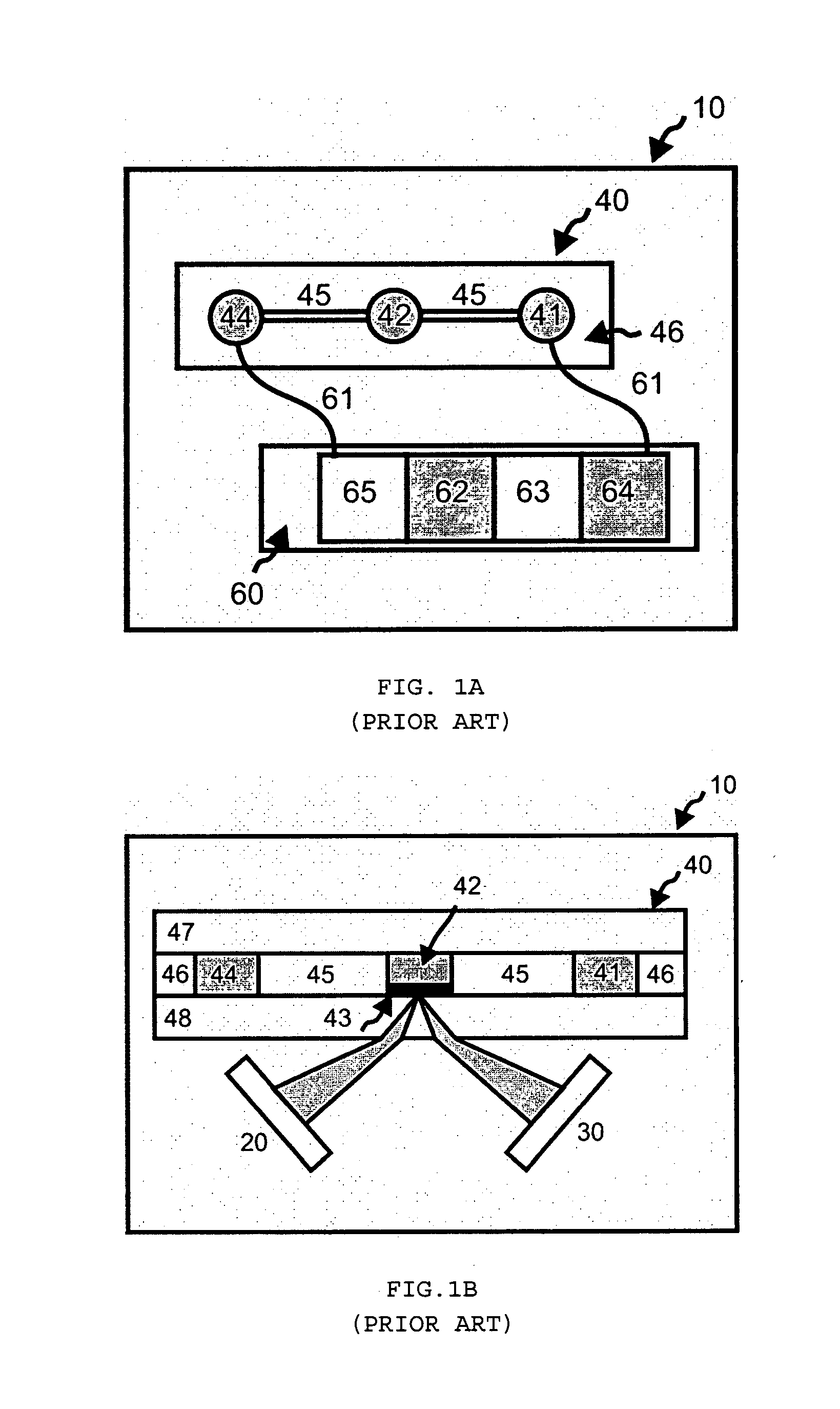
[0091]The previous example demonstrates that the present invention may be used to build and operate a SPR sensor 10 that does not require the use of external pumping or fluid control elements. In most practical cases, the use of the SPR sensor 10 for quantitative detection of chemical and / or biological events occurring at the DS 43 requires the use of different fluids flowing in and out of the DZ 42 in a sequential manner. These different fluids may be required for different functions (e.g. surface cleaning, fluid mixture, use of a secondary antibody, etc.). On the other hand, the process described in the first example implies a measure of the SPR effect in a dry surface right after fluid has passed the DZ 42 containing the DS 43. This may be difficult to accomplish in some cases and it may yield high experimental errors (e.g. if the DS 43 is highly hydrophilic then the complete removal of an aqueous fluid may be difficult to achieve).

[0092]Based on the principles already described,...

third example

[0104]The previous examples demonstrate the fact that the present invention may be used to build and operate a SPR sensor 10 that does not require the use of external pumping and fluid control elements but where the fluid flow is unidirectional (it is not possible to make the fluids return to their initial reservoirs). In some practical cases this fact is a limiting factor for the performance of the SPR sensor 10. In particular, if the substance to be detected is present in one of the fluids at a low concentration then it would e preferable to have that fluid passing several times on the DZ 42.

[0105]FIG. 5A shows a schematic top view of the RFS 40 of an SPR sensor 10 according to the present invention that enables the fluid passing several times on the DZ 42. The geometric dimensions of the different elements of RFS 40 are defined in such a way that the channels 45 and the DZ 42 present a combined volume smaller than the total fluid volume. In this case, the fluid will never be conf...


PUM


Abstract

The present invention describes a detection device based on the surface plasmon resonance effect, comprising: (1) a rotational microfluidic substrate (40) with channels (45), valves (50) and reservoirs (41,44) and at least one Detection Zone (42) wherein said Detection Zone comprises a Detection Surface (DS) built on top of a dif tractive thin electrically conductive layer, —(2) a system comprising a light emitter (20) and a light detector (30) capable of transducing the occurrence of events near the DS by exploiting the surface plasmon resonance effect in the diffractive conductive layer, —(3) a mechanism for controlling the rotation speed, duration and positioning of the rotational microfluidic substrate, in order to move a predefined liquid volume from an initial reservoir into a Detection Zone and finally into a final reservoir. The sensor described in the present invention enables the determination of the concentration of specific chemical and / or biological substances present at the DS or present in the fluid near the DS.

Description

TECHNICAL FIELD[0001]The present invention relates to electro-optic sensors based on the Grating mode of the Surface Plasmon Resonance (SPR) effect. In particular, the invention relates to chemical and / or biological detection devices and processes that include the following elements: (1) a Rotational Fluidic Substrate (RFS) containing channels, valves and reservoirs, and at least one Detection Zone (DZ) wherein a Detection Surface (DS) is built on top of a diffractive thin conductive layer; (2) a group of light emission and detection capable of transducing the occurrence of events near the DS into by exploiting the surface plasmon resonance effect in the diffractive conductive layer; (3) a mechanism for controlling the rotation speed, duration and positioning of the rotational microfluidic substrate, in order to move a predefined liquid volume from an initial reservoir into a DZ under controlled flow conditions.Chemical / Biological Detection Devices[0002]A Chemical / biological detecti...

Claims


Application Information

Patent Timeline
IPC IPC(8): G01N21/00
CPCB01L3/50273B01L2200/0621B01L2300/0654B01L2300/0806G01N21/553B01L2300/087B01L2400/0409B01L2400/0688G01N21/07B01L2300/0867
Inventor GARCIA DA FONSECA, JOAO
Owner BIOSURFIT
Why Eureka
Try Eureka