Sensor device

Inactive Publication Date: 2014-12-25
AISAN IND CO LTD
View PDF0 Cites 30 Cited by
  • Summary
  • Abstract
  • Description
  • Claims
  • Application Information

AI Technical Summary

Benefits of technology

[0006]the first electrode pair may be prevented from being exposed to the liquid by covering the first electrode pair with the protective film. As a result, the first electrode pair may he inhibited from corroding.
[0007]A dielectric constant of the liquid varies depending on the properties of the liquid, for example a concentration of a substance that is contained in the liquid, a temperature of the liquid, a degree of deterioration of the liquid, etc

Problems solved by technology

An electrode pair that is immersed in l

Method used


Image

  • Sensor device
  • Sensor device
  • Sensor device

Examples


Example

First Embodiment

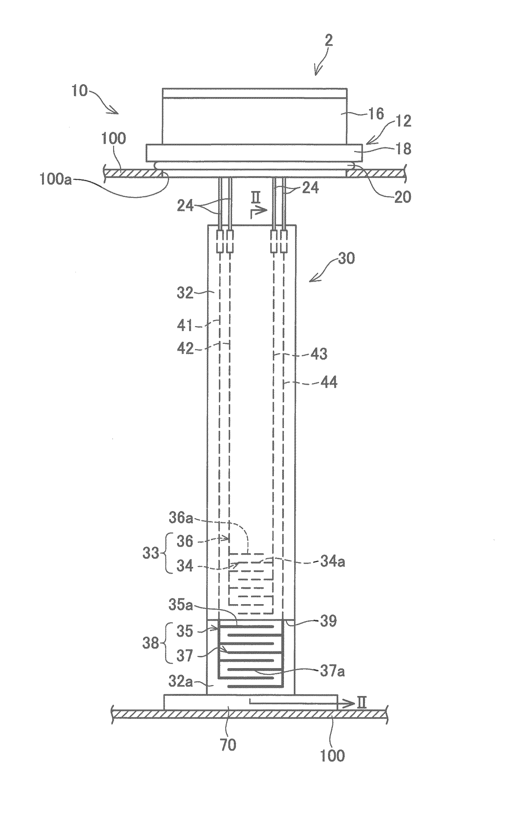
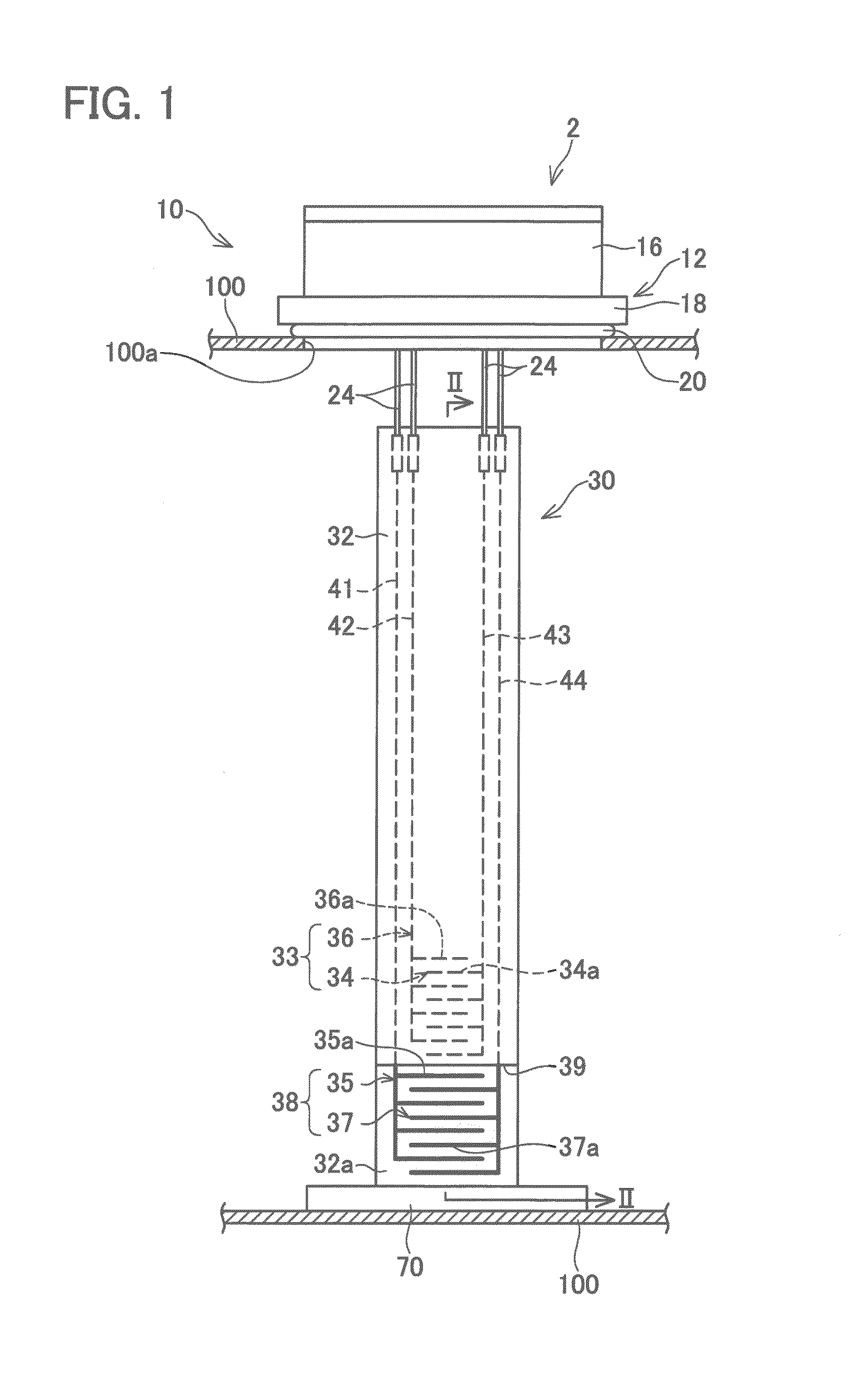
[0021]A sensor device 2 shown in FIG. 1 is mounted in a vehicle (e.g., an automobile). The vehicle runs on mixed fuel of gasoline and ethanol. The sensor device 2 is used for determining a concentration of ethanol in the fuel stored in a fuel tank 100. The sensor device 2 includes a control device 10 and a sensor 30.

[0022]The control device 10 is housed in a casing 12. The casing 12, attached to an opening 100a provided in an upper wall of the fuel tank 100, closes the opening 100a. The casing 12 includes a lid 18 and a housing case 16. The lid 18 is in the shape of a flat plate, an area of which is wider than an opening area of the opening 100a. The lid 18 has its outer edge portion in contact with the fuel tank 100 with a seal member 20 made of resin therebetween. The seal member 20 prevents the fuel from leaking through the opening 100a. Attached to an upper surface of the lid 18 is the housing case 16. The housing case 16 houses the control device 10. The housing...

Example

Second Embodiment

[0040]The second embodiment is described in terms of its differences from the first embodiment. A sensor device 2 of the second embodiment detects the liquid level of the fuel stored in the fuel tank 100 in addition to the ethanol concentration of the fuel. As shown in FIG. 4, an electrode pair 60 is arranged on a surface 32a of a substrate 32 in addition to electrode pairs 33 and 38.

[0041]The electrode pair 60 is located above the electrode pair 33 and between the two longitudinal electrodes 41 and 42. The electrode pair 60 is made of a thin-film electrically-conducting material (for example, an alloy containing either copper or silver). The electrode pair 60 is entirely covered with a protective film 39. The electrode pair 60 includes a reference electrode 62 and a signal electrode 64. The reference electrode 62 includes a plurality of (sixteen in FIG. 4) electrode portions 62a and a longitudinal electrode 63 (it should be noted that in FIG. 4 only one of the elec...

Example

Third Embodiment

[0046]The third embodiment is described in terms of its differences from the second embodiment. As shown in FIG. 6, an electrode pair 38 is arranged on a back surface 32b of the substrate 32. Further, as shown in FIG. 5, the electrode pair 33 is arranged close to the lower end of the surface 32a. As shown in FIG. 7, the protective film 39 entirely covers the surface 32a. It should be noted that there is no protective film placed on the back surface 32b, and the electrode pair 38 is entirely exposed to the fuel.

[0047]This configuration makes it possible to arrange the electrode pair 33 and the electrode pair 38 at the same height or, in particular, arrange the electrode portions 34a to 37a in a range of the same height. Immediately after fueling, the fuel stored in the fuel tank 100 may be distributed inhomogeneously in the direction of the height of the fuel tank. This configuration allows the electrode pair 33 and the electrode pair 38 to detect fuel having a unifor...


PUM


Abstract

Provided herein is a sensor device that may include a first electrode pair, a second electrode pair, and a detector. The first electrode pair may be covered with a protective film. The second electrode pair may have at least a portion thereof exposed to liquid. The detector may be configured to detect a property of the liquid by using a value concerning an electrical conductivity of the liquid as determined by using the second electrode pair and a value concerning a capacitance of the first electrode pair.

Description

CROSS-REFERENCE TO RELATED APPLICATION[0001]This application claims priority to Japanese Patent Application No. 2013-129517 filed on Jun. 20, 2013, the contents of which are hereby incorporated by reference into the present application.TECHNICAL FIELD[0002]This specification discloses a sensor device that detects properties of a liquid by using an electrode pair.DESCRIPTION OF RELATED ART[0003]Japanese Patent Application Publication No. 2005-351688 discloses a liquid level and liquid property sensor including a plurality of electrode pairs. Each of the plurality of electrode pairs is used with at least a portion thereof immersed in liquid.SUMMARY[0004]An electrode pair that is immersed in liquid is easily corroded by the liquid. In this specification, a technology is provided that may properly detect the properties of liquid while inhibiting corrosion of an electrode pair.[0005]A sensor device disclosed herein comprises: a first electrode pair covered with a protective film; a secon...

Claims


Application Information

Patent Timeline
IPC IPC(8): G01N27/22E21B49/08G01N27/02G01V3/00
CPCG01N27/221G01N27/02E21B49/08G01V3/00
Inventor IKEYA, MASAKI
Owner AISAN IND CO LTD
Why Eureka
Try Eureka