Inflatable chamber device for motion through a passage

a chamber device and motion technology, applied in medical devices, catheters, diagnostics, etc., can solve the problems of inability to push the active head, possible injuries to the inner tissue walls of the lumen, and complicating both the control system and the physical deployment of the device within the passageway, so as to achieve efficient use of such devices

Active Publication Date: 2010-01-28
TECHNION RES & DEV FOUND LTD
View PDF26 Cites 18 Cited by
  • Summary
  • Abstract
  • Description
  • Claims
  • Application Information

AI Technical Summary

Benefits of technology

[0012]The present invention seeks to provide new methods and devices for use in serial inflatable balloon self-propulsion devices, for motion along internal passageways, having features which are enabling for efficient use of such devices.

Problems solved by technology

The ability to crawl through long, flexible, and curved tubes has long been a challenge for engineers since numerous applications can benefit from a reliable solution.
In some type of applications it is impossible to push the active head from the back because the force required would cause buckling of the long rod or wire.
One of the biggest shortcomings of current endoscopes and catheters is that they are pushed into the human body manually over a curved path, thereby causing friction, and possible injuries to the inner tissue walls of the lumen.
Most of the above described devices have the disadvantage that a number of control lines or pneumatic tubes are required to operate the device, which complicates both the control system and the physical deployment of the device within the passageway.
Many of the above described devices may have various disadvantages which limit their usefulness in one aspect or another, such that there is need for a new, distally propelled catheter head which can operate simply, over long tracts of internal passages, and without causing undue damage to the inner walls of the passages.

Method used


Image

  • Inflatable chamber device for motion through a passage
  • Inflatable chamber device for motion through a passage
  • Inflatable chamber device for motion through a passage

Examples


Embodiment Construction

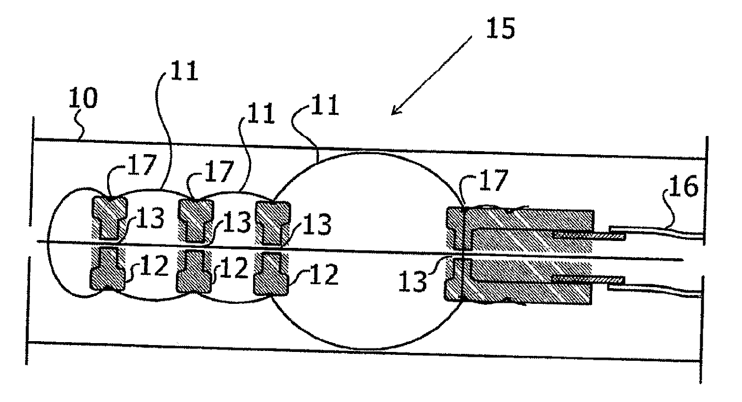
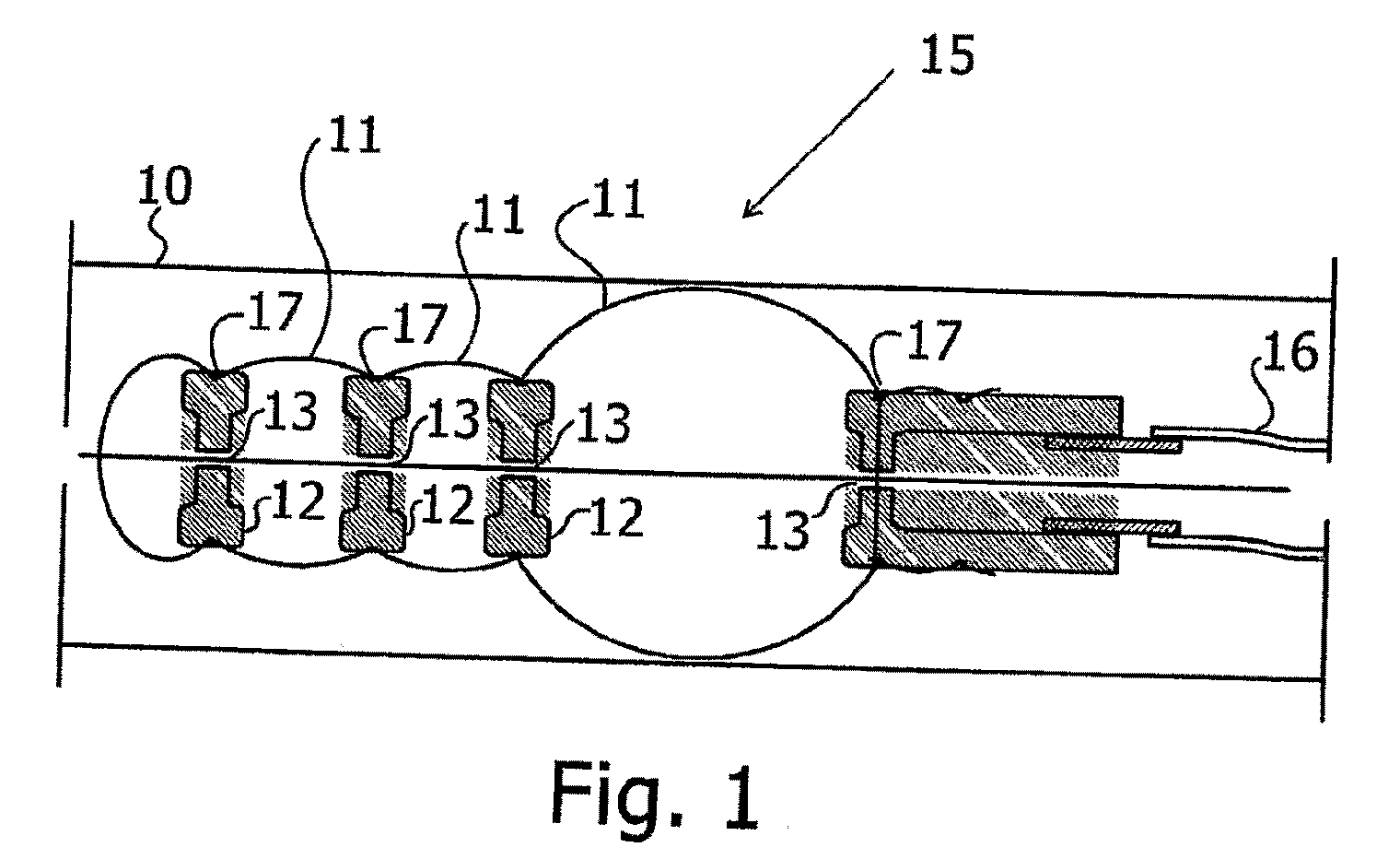
[0079]Reference is now made to FIG. 1, which illustrates schematically a tip-propelled catheter device 15 for traveling down a lumen 1, as is known in the art. The device may preferably comprise a number of balloons 11 connected to each other by separators 12 with one or more small openings, preferably in the form of orifices 13 formed therein, such that all the balloons comprise a single volume, inflatable through a single input. For ease of construction, the device can alternatively and preferably comprise a single inflatable balloon divided into separate balloon segments by separators with orifices such that the entire segmented balloon can be inflated through a single input. The balloon fabric is preferably held in place relative to the separators 12 by means of rings 17 or glued or molded to the separators. Whichever preferred construction is used, the device is connected by a single tube 16 to a fluid supply for inflating the balloons or the balloon segments. For the sake of s...


PUM


Abstract

A self-propelled device for locomotion through a lumen, comprising a set of serially arranged inflatable chambers, and incorporating a number of novel aspects. To enable easy insertion and use, the rigidity of the device is increased by means of rigid inserts in the balloons, or by use of stiff springs between segments. The working channel can be attached to the distal chamber of the device, such that it is pulled from the leading end of the device during inflation, rather than being pulled from the trailing end of the device during deflation. Lumen wall inspection or treatment facilities are enabled by means of a camera or treatment arm mounted between two distally positioned balloons, the device is able to provide observation capabilities to the lumen wall, yet without becoming excessively dirty by exposure to the front end of the device, as in prior art camera units.

Description

FIELD OF THE INVENTION[0001]The present invention relates to the field of inflatable devices capable of self propelled motion through tubes, especially for endoscopic and vascular use.BACKGROUND OF THE INVENTION[0002]The ability to crawl through long, flexible, and curved tubes has long been a challenge for engineers since numerous applications can benefit from a reliable solution. This ranges from medical applications for treatment and diagnosis to sewer pipes, gas pipes and power plants.[0003]Current solutions often contain a payload such as a camera, that is pushed from the back by a long flexible rod or wire. This is the solution currently used in most medical applications with guide wires or catheters as used to deliver diagnosis or treatment instruments to the desired position, e.g. catheterization, colonoscopy, ureteroscopy, dilating balloon, and others.[0004]In some type of applications it is impossible to push the active head from the back because the force required would c...

Claims


Application Information

Patent Timeline
Patent Type & Authority Applications(United States)
IPC IPC(8): A61M31/00
CPCA61B17/12045A61B17/12136A61B2017/00557A61B2017/12127F01B19/00A61B2019/5206A61B2019/5217A61M25/0122A61B2017/22055A61M25/0116A61B2090/306A61B2090/3614
Inventor HASSIDOV, NOAMGLOZMAN, DANIELSHOHAM, MOSHE
Owner TECHNION RES & DEV FOUND LTD
Why Eureka
Try Eureka