Method for handling data

a data and data technology, applied in multiplex communication, instruments, generating/distributing signals, etc., can solve the problems of data transmission in time-delayed and discontinuous manner, and achieve cost-effective effects

Inactive Publication Date: 2010-01-28
ROBERT BOSCH GMBH
View PDF7 Cites 0 Cited by
  • Summary
  • Abstract
  • Description
  • Claims
  • Application Information

AI Technical Summary

Benefits of technology

[0018]By introducing the new protocol for controlling, which typically gets along without additional handshake, clock, and sync signals, it is possible to transmit a data flow within the system, for example, from the central processor to the output stage or valve output stage, a minimal number of lines, in particular only one line, being required.
[0019]Components of the protocol, which are designed as synchronization blocks, such as re-sync blocks and master-sync blocks, allow for the quick new synchronization and the resynchronization between data blocks. Furthermore, the synchrony of transmitter and receiver may be used via a basic clock pulse for the cost-effective implementation of the receiver.

Problems solved by technology

However, such protocols use only one part of the possibilities that exist for short-distance transmissions, such as between a computer and a valve output stage, for example.
Of course, the data may also be transmitted in a time-delayed manner as well as discontinuously.

Method used


Image

  • Method for handling data
  • Method for handling data
  • Method for handling data

Examples


Embodiment Construction

[0038]Example embodiments of the present invention are represented schematically in the drawing, and are described in detail below with reference to the drawing.

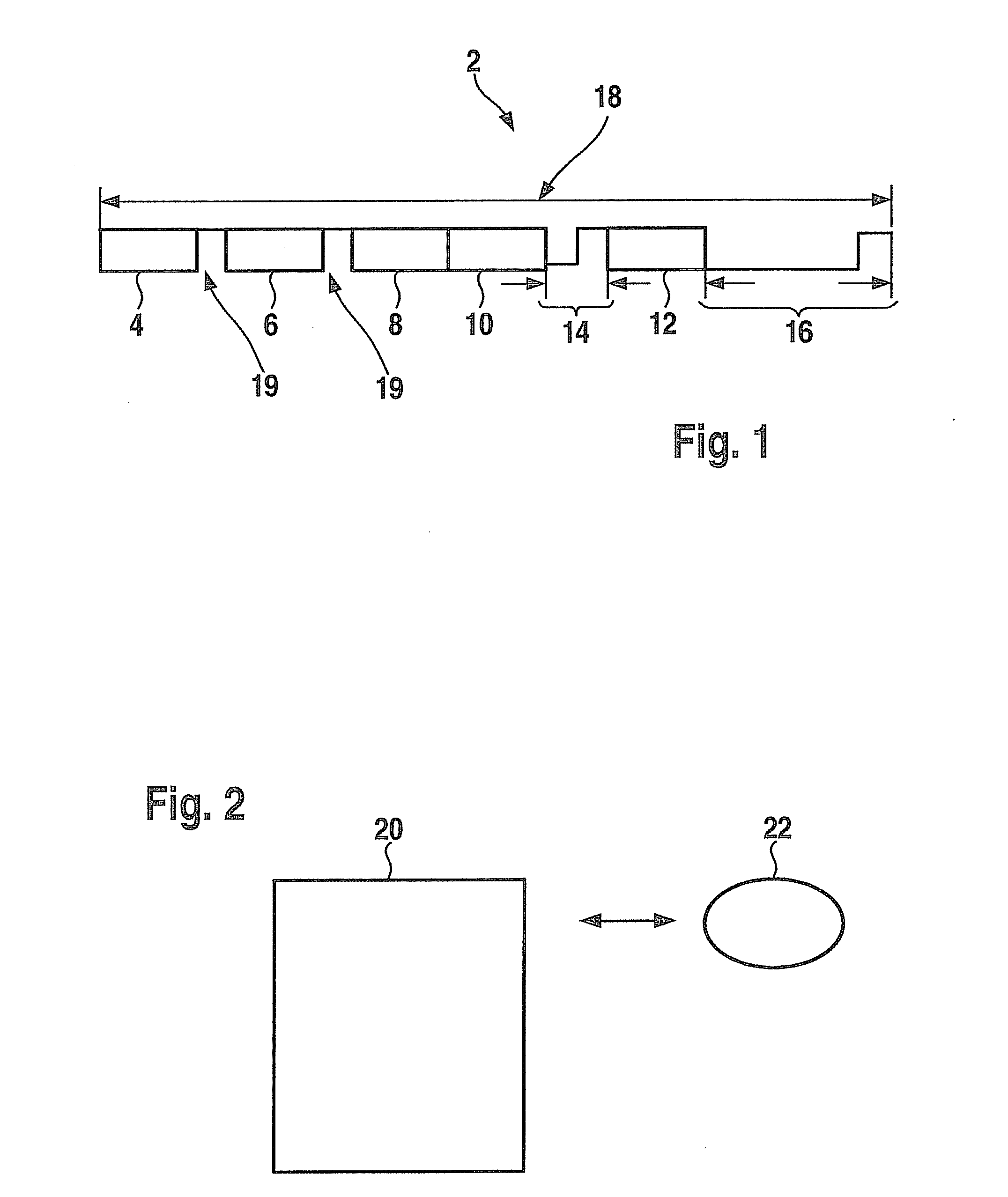
[0039]FIG. 1 shows an example embodiment of a serial protocol 2 for valve control of two valves, the protocol having one data block 4, 6, 8, 10, 12 respectively for one task respectively, and one frequency or period duration per valve. In this context, the following is provided: a first data block 4 for a “valve control parameter value 1,” a second data block 6 for a “valve control parameter value 2,” a third data block 8 for a “valve control parameter value 3,” a fourth data block 10 for a “valve control parameter value 4,” and a fifth data block 12 for “aux,” in which auxiliary information for different functions is stored. This auxiliary information is provided for data synchronization, for controlling monitoring and test procedures, or for turning on and off valves and other functions, for example. Existing protocol 2 fu...


PUM


Abstract

A method for handling data in which a serial data flow, with which a plurality of data is transmitted simultaneously per line, is transmitted using a serial protocol, which is formed from data blocks and synchronization blocks.

Description

FIELD OF THE INVENTION[0001]The present invention relates to a method for handling data, a device for handling data, a computer program, and a computer program product.BACKGROUND INFORMATION[0002]Normally pulse-width modulation signals (PWM signals) or serial interfaces having so-called handshake lines, timing circuits, and sync lines are used to control valve output stages. Serial protocols, which require additional handshake lines, timing circuits, and sync lines, are designed for longer transmission paths. However, such protocols use only one part of the possibilities that exist for short-distance transmissions, such as between a computer and a valve output stage, for example. They use a possibly existing synchrony of transmitter and receiver just as little. Apart from this, to synchronize, these protocols need a resting phase on the line, which is why they are not presently used in control units.[0003]A method for controlling a control element is described in DE 199 50 027. In t...

Claims


Application Information

Patent Timeline
Patent Type & Authority Applications(United States)
IPC IPC(8): G06F1/04
CPCG08C15/06H04L7/041H04J3/0614
Inventor RUPP, ANDREASBAUMGAERTNER, RAINER
Owner ROBERT BOSCH GMBH
Why Eureka
Try Eureka