Thermoelectric power generator for variable thermal power source

a variable thermal power source and generator technology, applied in the manufacture/treatment of thermoelectric devices, machines/engines, mechanical equipment, etc., can solve the problems of reducing device performance, performance degradation compared to design values, and exposed thermoelectric power generators

Inactive Publication Date: 2010-02-04
GENTHERM INC
View PDF107 Cites 67 Cited by
  • Summary
  • Abstract
  • Description
  • Claims
  • Application Information

AI Technical Summary

Benefits of technology

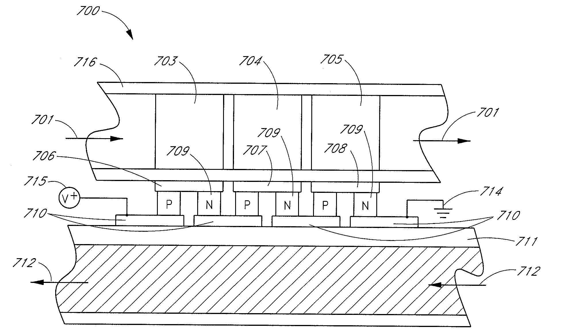
[0015]In certain embodiments, a thermoelectric generator comprises an input portion configured to allow a working fluid to flow therethrough. The thermoelectric generator further comprises an output portion configured to allow the working fluid to flow therethrough. The thermoelectric generator further comprises a plurality of elongate thermoelectric segments substantially parallel to one another. At least one of the thermoelectric segments comprises at least one thermoelectric module. Each thermoelectric segment is configurable to allow the working fluid to flow therethrough from the input portion to the output portion. The thermoelectric generator further comprises at least one movable element positionable to allow flow of the working fluid through at least a first thermoelectric segment of the plurality of thermoelectric segments and to inhibit flow of the working fluid through at least a second thermoelectric segment of the plurality of thermoelectric segments.

Problems solved by technology

Under many operating conditions, however, thermoelectric power generators are exposed to a combination of changing heat fluxes, hot side heat source temperatures, cold side heat rejection temperatures, and other variable conditions.
In addition, the device properties, such as TE thermal conductance, Figure of Merit Z, heat exchanger performance all have a range of manufacturing tolerances that combine to, in general, reduce device performance.
As a result, performance varies and operation at a predetermined set point can lead to performance degradation compared to design values.
Any process that consumes energy that is not 100% efficient generates waste energy, usually in the form of heat.
For example, internal combustion engines generate a substantial amount of waste heat.
However, because the exhaust system varies greatly in heat and heat flux, providing a system that is effective has been illusive.
By way of example, compared to optimal performance, degradation in automobile waste heat recovery system performance can be very significant, amounting to at least 30%.

Method used


Image

  • Thermoelectric power generator for variable thermal power source
  • Thermoelectric power generator for variable thermal power source
  • Thermoelectric power generator for variable thermal power source

Examples


Embodiment Construction

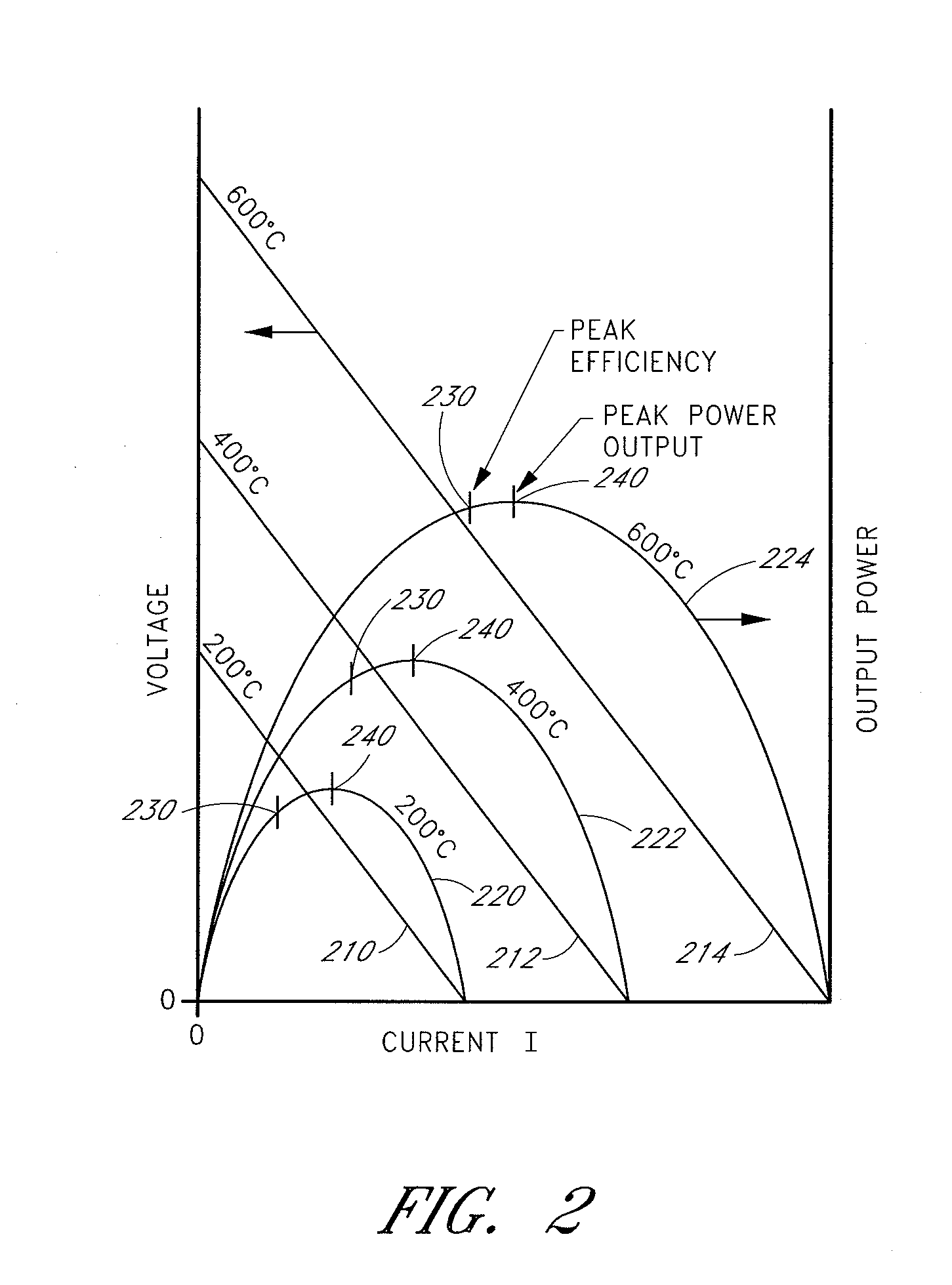
[0040]Certain embodiments described herein relate to a thermoelectric power generation system which is capable of generating power more efficiently than a standard system, particularly suited for a thermal power source with variable thermal output. Certain embodiments are useful for many waste heat recovery, waste heat harvesting and power generation applications. However, in order to illustrate various aspects of the thermoelectric power generation system, a specific embodiment is described which generates electrical power from thermal power contained in the exhaust of a vehicle. This particular example illustrates the advantage of designing the power generation system to monitor and control the conditions that affect power production, even under varying operating conditions. Substantial improvements can be derived by controlling TE couple properties (for example as described in U.S. Pat. No. 6,672,076, entitled “Efficiency Thermoelectrics Utilizing Convective Heat Flow” and incorp...


PUM


Abstract

A thermoelectric generator includes a first thermoelectric segment including at least one thermoelectric module. The first thermoelectric segment has a working fluid flowing therethrough with a fluid pressure. The thermoelectric generator further includes a second thermoelectric segment including at least one thermoelectric module. The second thermoelectric segment is configurable to allow the working fluid to flow therethrough. The thermoelectric generator further includes at least a first variable flow element movable upon application of the fluid pressure to the first variable flow element. The first variable flow element modifies a flow resistance of the second thermoelectric segment to flow of the working fluid therethrough.

Description

CLAIM OF PRIORITY[0001]This application claims the benefit of priority to U.S. Provisional Patent Application No. 61 / 084,606 filed Jul. 29, 2008 which is incorporated in its entirety by reference herein.STATEMENT REGARDING FEDERALLY SPONSORED R&D[0002]The U.S. Government may claim to have certain rights in this invention or parts of this invention under the terms of Contract No. DE-FC26-04NT42279 awarded by the U.S. Department of Energy.BACKGROUND OF THE INVENTION[0003]1. Field of the Invention[0004]The present application relates to the field of thermoelectric power generation, and more particularly to systems for improving the generation of power from thermoelectrics where the heat source varies in temperature and heat flux.[0005]2. Description of the Related Art[0006]Thermoelectrics are solid state devices that operate to become cold on one side and hot on the other side when electrical current passes through. They can also generate power by maintaining a temperature differential...

Claims


Application Information

Patent Timeline
Patent Type & Authority Applications(United States)
IPC IPC(8): H01L35/02
CPCF01N5/025Y02T10/16H01L35/30Y02T10/12H10N10/13
Inventor BELL, LON E.CRANE, DOUGLAS T.
Owner GENTHERM INC
Why Eureka
Try Eureka