Power Plant

a power plant and power technology, applied in the direction of propulsion parts, propulsion using engine-driven generators, electric devices, etc., can solve the problems of preventing the attainment of sufficient power generation efficiency and lowering the driving efficiency of the power uni

Inactive Publication Date: 2010-02-04
HONDA MOTOR CO LTD
View PDF11 Cites 19 Cited by
  • Summary
  • Abstract
  • Description
  • Claims
  • Application Information

AI Technical Summary

Benefits of technology

[0017]As described above, the power from the prime mover is divided and transmitted to the driven parts via three paths, i.e. a first path formed by the second rotor, associated magnetic circuits and the first rotor, a second path formed by the third rotor, associated magnetic circuits and the fourth rotor, and a third path formed by the second rotor, associated magnetic circuits, the first stator, the first and second controllers, the second stator, associated magnetic circuits and the fourth rotor. In the third path, the power from the prime mover is once converted to electric power, and is then converted back into power to be transmitted to the driven parts via a so-called electrical path, whereas in the first and second paths, the power is transmitted to the driven parts without being converted to electric power, via the magnetic circuits in a non-contacting manner, via a so-called magnetic path, so that the transmission efficiency is high compared with the third path.
[0041]As described above, according to the present invention, it is possible to drive the driven parts by the first generator-motor and / or the second generator-motor, without using the power from the prime mover. Further, in this case, it is possible not only to block reverse rotation of the output shaft of the prime mover by the brake mechanism but also to drive the driven parts without dragging the prime mover by the following effects: The electric power-converted power from the first stator acts on the second rotor such that the second rotor is caused to rotate in the second rotor blocking direction, and the electric power-converted power from the second stator acts on the third rotor such that the third rotor is caused to rotate in the third rotor blocking direction. Thus, during the above-described driving of the driven parts, the output shaft of the prime mover is held in a stopped state together with the second and third rotors, which prevents the prime mover from being dragged.

Problems solved by technology

Further, since the induction machine is formed by the first stator and the intermediate rotor, when the electric power is generated by the above-mentioned first stator, Joule heat is generated not only in the coil of the first stator but also in the coil of the intermediate rotor, which prevents the sufficient power generation efficiency from being obtained, to further lower the driving efficiency of the power unit.

Method used


Image

  • Power Plant
  • Power Plant
  • Power Plant

Examples


first embodiment

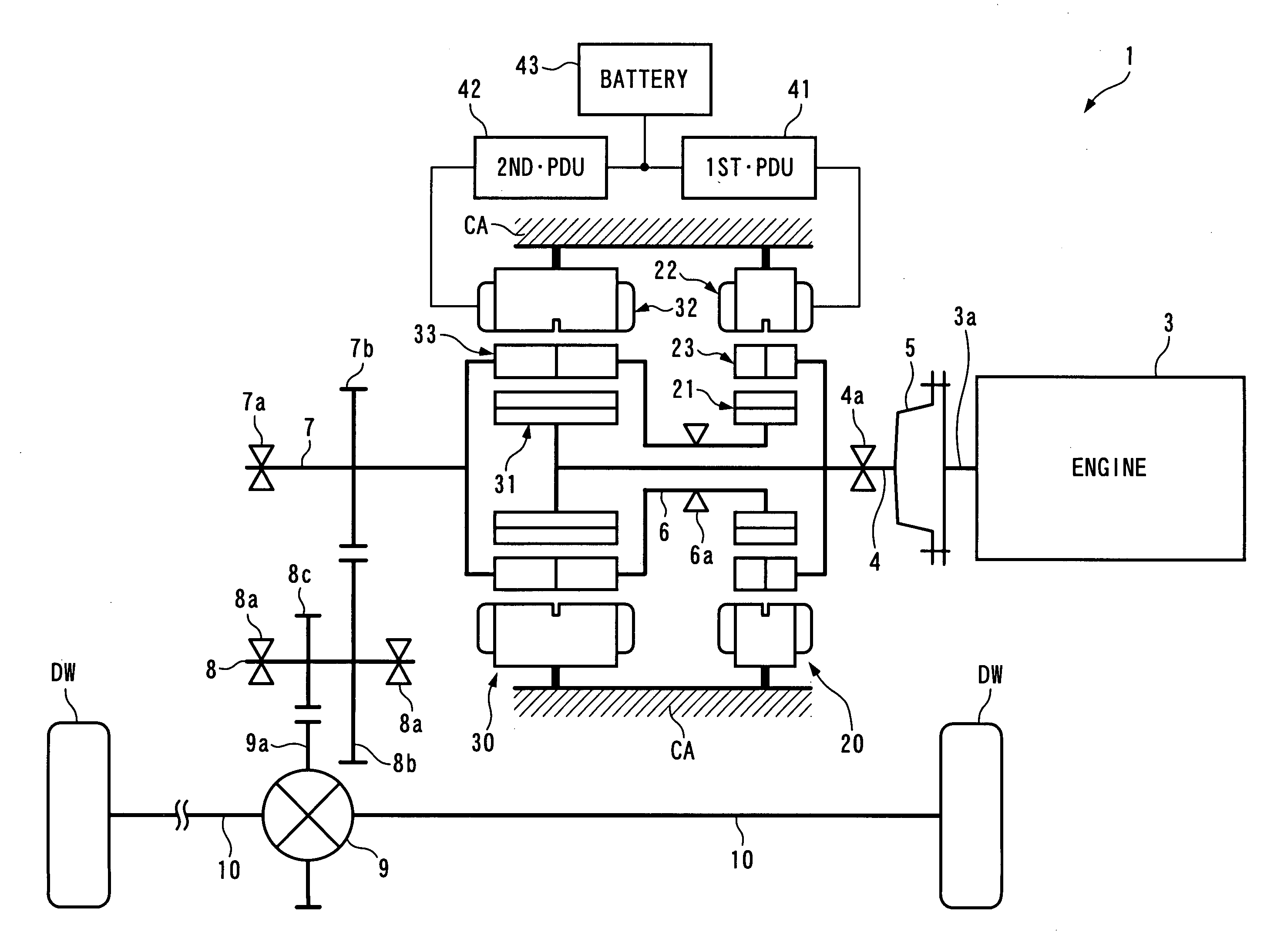
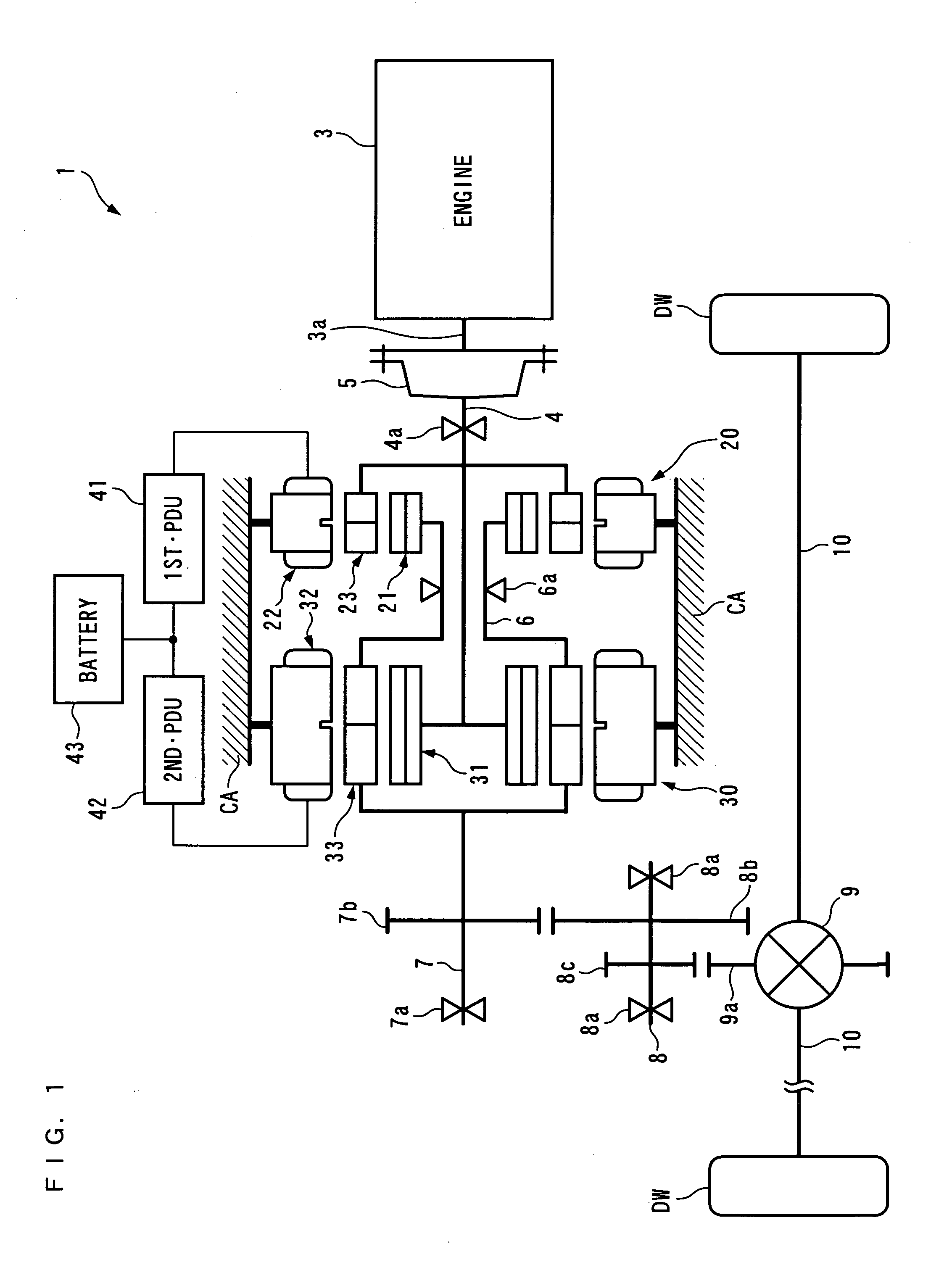
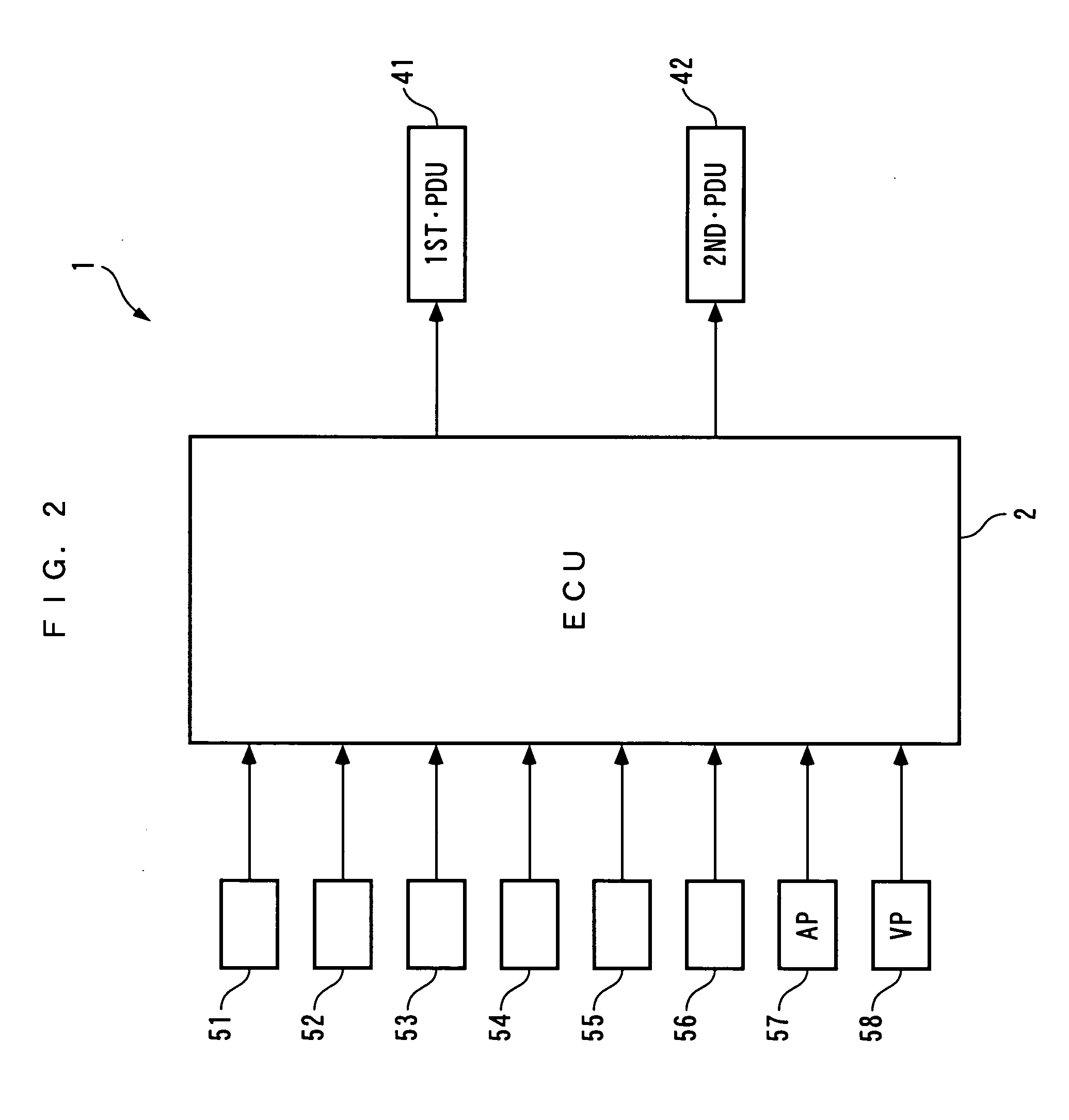
[0079]The present invention will now be described in detail with reference to the drawings showing a preferred embodiment thereof. It should be noted that in the figures, hatching for portions illustrating cross-sections are omitted for convenience. FIGS. 1 and 2 schematically show a power plant 1 according to the present embodiment. As shown in FIG. 1, the power plant 1 is for driving left and right drive wheels DW and DW (driven parts) of a vehicle (not shown), and, as shown in FIG. 1, includes an internal combustion engine 3 (prime mover) and a first generator-motor 20 and a second generator-motor 30 as power sources, and a differential gear mechanism 9 connected to the drive wheels DW and DW via drive shafts 10 and 10. Further, as shown in FIG. 2, the power plant 1 includes an ECU 2 (first controller and second controller), a 1st•PDU 41 (first controller) and a 2nd•PDU 42 (second controller), for controlling the operations of the internal combustion engine 3 and the first and se...

third embodiment

[0230]In the power plant 1B shown in FIG. 34, the transmission 70 is the gear-type stepped transmission including an input shaft 70a and an output shaft (not shown), a plurality of gear trains different in gear ratio from each other, and clutches (not shown) for engaging and disengaging respectively between the gear trains, and the input shaft 70a and the output shaft. The transmission 70 changes the speed of power inputted to the input shaft 70a by using one of the gear trains, and outputs the power to the output shaft. Further, in the transmission 70, a total of four speed positions, i.e. a first speed (transmission gear ratio=the rotational speed of the input shaft 70a / the rotational speed of the output shaft>1.0), a second speed (transmission gear ratio=1.0), a third speed (transmission gear ratio2 controls a change between these speed positions.

[0231]Further, in the power plant 1B, differently from the first embodiment, the gear 7b is not provided on the second main shaft 7, a...

fifth embodiment

[0244]In the power plant 1D shown FIG. 36, the transmission 90 is a gear-type stepped transmission formed by a planetary gear unit and so forth, and includes an input shaft 90a and an output shaft (not shown). In the transmission 90, a total of two speed positions, i.e. a first speed (transmission gear ratio=the rotational speed of the input shaft 90a / the rotational speed of the output shaft=1.0) and a second speed (transmission gear ratio2 performs a change between these speed positions. Further, the input shaft 90a of the transmission 90 is directly connected to the flywheel 5, and the output shaft (not shown) thereof is directly connected to the aforementioned first main shaft 4. As described above, the transmission 90 is provided between the crankshaft 3a and the A2 and B1 rotors 23 and 31, for transmitting the engine power WENG to the A2 rotor 23 and the B1 rotor 31 while changing the speed of the engine power WENG. Furthermore, the number of the gear teeth of the gear 9a of t...


PUM


Abstract

There is provided a power plant which is capable of enhancing driving efficiency with which the power plant drives driven parts. The power plant 1 for driving the driven parts DW and DW includes a prime mover 3, and first and second generator-motors 20, 30. The first generator-motor 20 is comprised of a first stator 22, a first rotor 21 formed by magnets, and a second rotor 23 formed by soft magnetic material elements and disposed between the first stator 22 and the first rotor 21. The second generator-motor 30 is comprised of a second stator 32, a third rotor 31 formed by magnets, and a fourth rotor 33 formed by soft magnetic material elements and disposed between the second stator 32 and the third rotor 31. The first and fourth rotors 21, 33 are mechanically connected to the driven parts DW and DW, and the second and third rotors 23, 31 are mechanically connected to an output shaft 3a of the prime mover 3. The first and second stators 22, 32 are electrically connected to each other via first and second controllers 2, 41, 42.

Description

FIELD OF THE INVENTION[0001]The present invention relates to a power unit for driving driven parts, and more particularly to a power unit including an internal combustion engine and two generator-motors.BACKGROUND ART[0002]Conventionally, as a power unit of this kind, one disclosed e.g. in Patent Literature 1 is known. This power unit is for driving left and right drive wheels of a vehicle, and is provided with an internal combustion engine, and first and second generator-motors. The first generator-motor has a first stator formed by a plurality of armatures, an intermediate rotor formed by an iron core and a coil, and an inner rotor formed by a permanent magnet. The first stator, the intermediate rotor, and the inner rotor are arranged in this order from the inside to the outside in a radial direction. Further, in the first generator-motor, an induction machine is formed by the first stator and the intermediate rotor, and a synchronous machine is formed by the intermediate rotor an...

Claims


Application Information

Patent Timeline
Patent Type & Authority Applications(United States)
IPC IPC(8): B60K6/48H02K47/20H02K16/02B60L50/16
CPCB60K1/02Y02T10/7275B60K6/448B60K2006/262B60L11/12B60L15/2054B60L2220/52B60W10/06B60W10/08B60W20/00F16H2037/102H02K51/00Y02T10/6243Y02T10/6286Y02T10/641Y02T10/646Y02T10/7077Y10S903/906Y02T10/648B60K6/26B60K6/40B60L3/0061B60L50/15B60L50/16B60L50/40B60L50/61B60L58/15B60L2210/40B60L2220/14B60L2220/50B60L2240/12B60L2240/421B60L2240/423B60L2240/441B60L2240/443B60L2240/545B60L2240/547B60L2240/549B60L2270/145H02K7/006H02K16/02H02K21/12Y02T10/62Y02T10/64Y02T10/70Y02T10/7072Y02T10/72B60W10/10B60W20/30
Inventor ABE, NORIYUKIAKUTSU, SHIGEMITSU
Owner HONDA MOTOR CO LTD
Why Eureka
Try Eureka