Electric power supply system

a technology of electric power supply and power supply system, which is applied in the direction of motor/generator/converter stopper, dynamo-electric converter control, battery/fuel cell control arrangement, etc., can solve the problems of certain degree of deterioration of insulation between the fuel cell system and the surrounding, the difficulty of maintaining such a high degree of insulation stably, and the loss of insulation type converters. , to achieve the effect of reducing the loss of insulation type converters

Inactive Publication Date: 2010-02-04
TOYOTA JIDOSHA KK
View PDF9 Cites 7 Cited by
  • Summary
  • Abstract
  • Description
  • Claims
  • Application Information

AI Technical Summary

Benefits of technology

[0025]More specifically, for example, said converter control means may change said effective turns ratio based on the relative ratio of electric power required by said drive apparatus and electric power generated by said first power source apparatus so that voltage conversion efficiency in said insulation type converter for system is maintained in a certain preferable condition. The voltage conversion efficiency (or the converter efficiency) of the insulation type converter for system depends on the turns ratio of the primary coil and the secondary coil. Therefore, the converter control means adjusts the effective turns ratio based on the aforementioned relative ratio so that the aforementioned preferable condition that provides more preferred conversion efficiency is achieved, thereby reducing loss in the insulation type converter for system.

Problems solved by technology

However, it is difficult to maintain such a high degree of insulation stably in some cases.
Causes for this may include, for example, that the electric power supply system necessarily contains a factor that leads to a decrease in the insulation performance (but technically needs to be contained in the electric power supply system) and that there is an external factor outside of the electric power supply system.
However, the presence of the cooling apparatus necessarily causes a certain degree of deterioration in insulation between the fuel cell system and the surrounding.

Method used


Image

  • Electric power supply system
  • Electric power supply system
  • Electric power supply system

Examples


embodiment 1

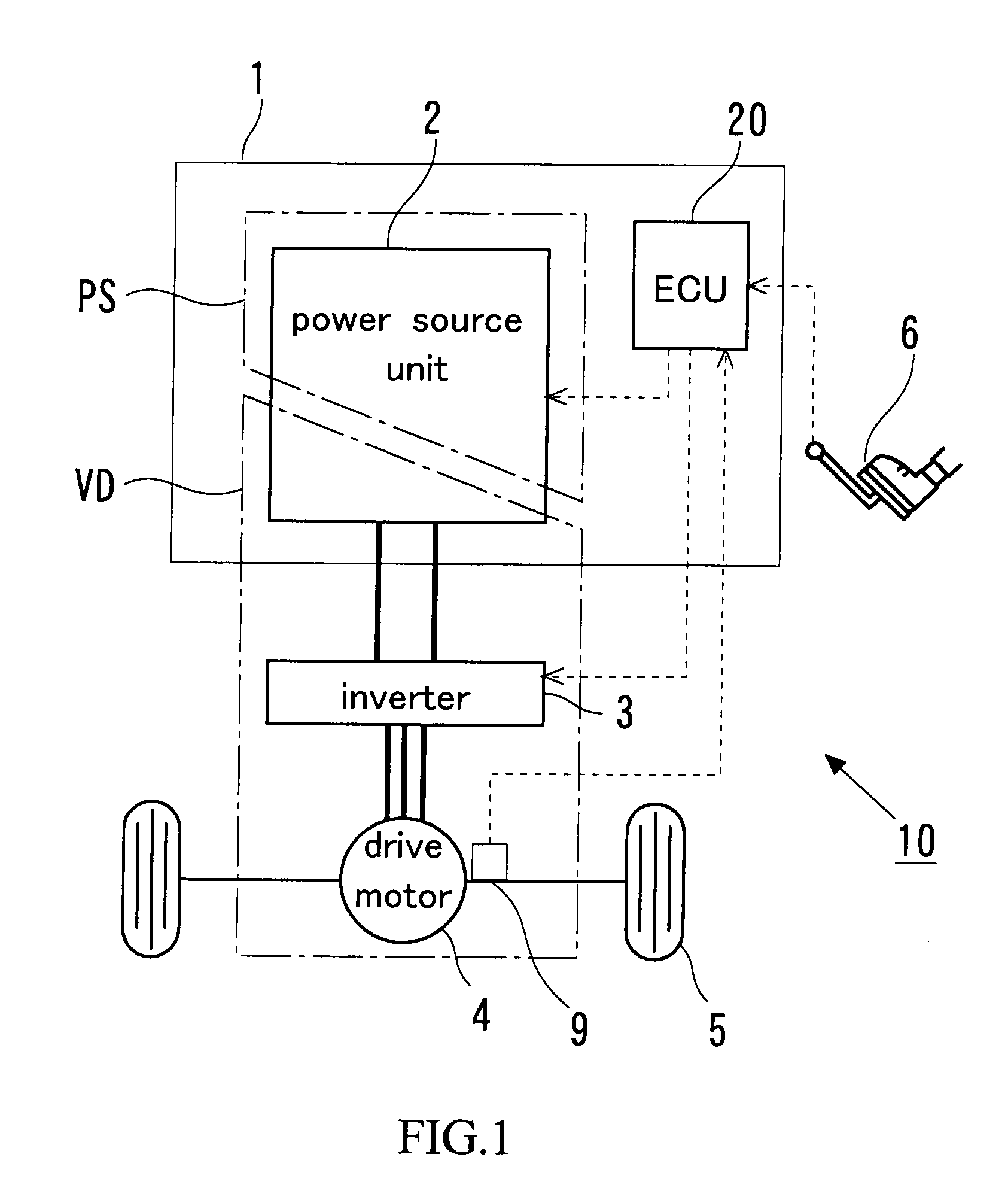
[0047]FIG. 1 schematically shows a vehicle 10 or a mobile body that is equipped with a fuel cell system 1, which constitutes the electric power supply system according to the present invention, and uses electric power supplied by the fuel cell system 1 as a drive source. The vehicle 10 is movable, or self-propelled as driving wheels 5 are driven by a drive motor (which will be simply referred to as the “motor” hereinafter) 4. The motor 4 is what is called a three phase alternating current motor, which is supplied with alternating current power from an inverter 3. The inverter 3 is supplied with direct current power from a power source unit 2 and converts the direct current power into alternating current power.

[0048]The vehicle 10 is further equipped with an electronic control unit (which will be hereinafter referred to as the “ECU”) 20, to which the aforementioned power source unit 2 and the inverter 3 are electrically connected, and electric power supply from the power source unit ...

embodiment 2

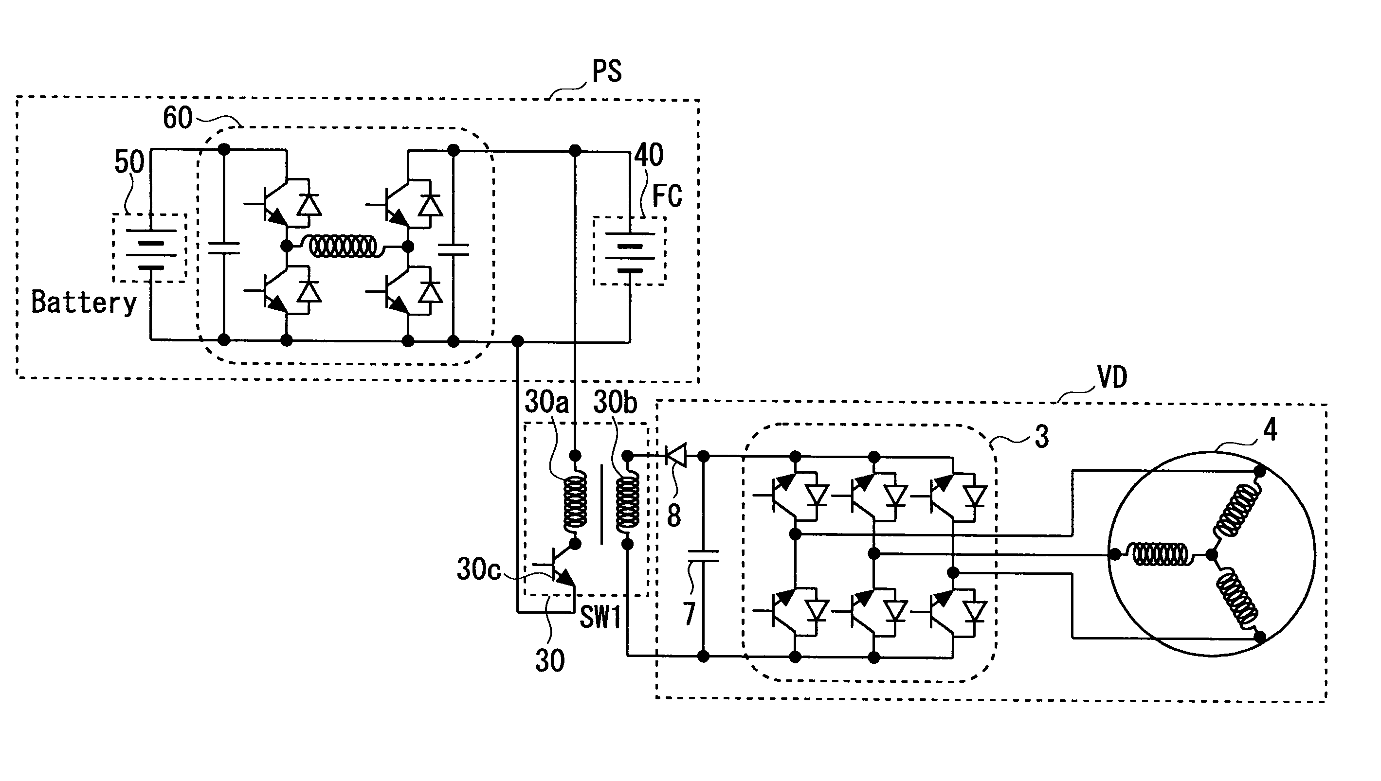
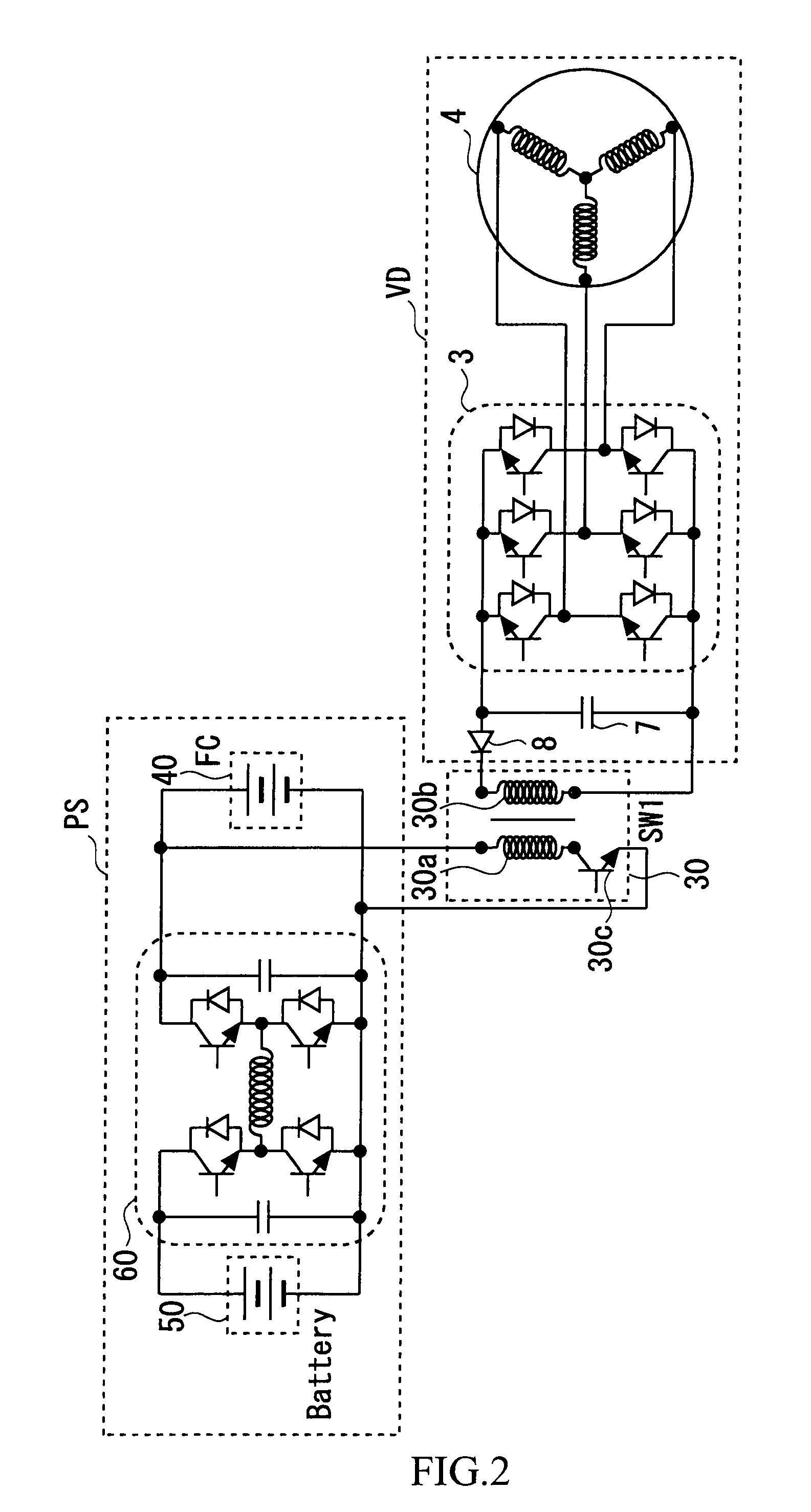
[0063]A second embodiment of the fuel cell system as an electric power supply system according to the present invention will be described with reference to FIG. 5. FIG. 5 is a diagram showing the general configuration of the electric power system of the vehicle 10. Components of the electric power system shown in FIG. 5 that are the same as the components of the electric power system shown in FIG. 2 are denoted by the same reference numerals, and detailed description thereof will be omitted. The electric power system shown in FIG. 5 differs from the electric power system shown in FIG. 2 in the DC to DC converter that connects the fuel cell 40 and the battery 50 in the electric power supply section PS.

[0064]The DC to DC converter used in this embodiment is a DC to DC converter 60b having what is called a half-bridge configuration. The voltage output regulated by this converter is different from that in the case of the converter having a full-bridge configuration, but the DC to DC con...

embodiment 3

[0065]A third embodiment of the fuel cell system as an electric power supply system according to the present invention will be described with reference to FIGS. 6 and 7. FIGS. 6 and 7 are diagrams each showing the general configuration of the electric power system of the vehicle 10. Components of the electric power systems shown in FIGS. 6 and 7 that are the same as the components of the electric power system shown in FIG. 2 are denoted by the same reference numerals, and detailed description thereof will be omitted.

[0066]First, the electric power system shown in FIG. 6 differs from the electric power system shown in FIG. 2 in the position at which the insulation type converter for system 30 is connected in the electric power supply section PS. In this embodiment, the primary coil 30a of the insulation type converter for system 30 and the switching element 30c, which are connected in series with each other, are connected in parallel with the battery 50 and connected to the DC to DC ...


PUM


Abstract

An electric power supply system, equipped on a mobile body to supply electric power to a drive apparatus that functions as a drive source of the mobile body, that includes a first power source apparatus that generates and supplies electric power to the drive apparatus, a second power source apparatus provided separately from the first power source apparatus and that supplies electric power to the drive apparatus, an insulation type converter provided between an electric power supply section including at least one of the first power source apparatus and the second power source apparatus, and a mobile body drive section including the drive apparatus, and ensuring insulation between these sections while transmitting electric power from the electric power supply section to the mobile body drive section. An increase in the supply voltage and adequate insulation performance can both be achieved when supplying power to a drive apparatus.

Description

TECHNICAL FIELD[0001]The present invention relates to an electric power supply system that supplies electric power to a drive apparatus, for example, to a system for supplying electric power from a fuel cell that produces electric power by an electrochemical reaction to a drive apparatus.BACKGROUND ART[0002]In recent years, fuel cells have drawn attention as electric power sources advantageous in operation efficiency and environment-friendliness. In a fuel cell, the amount of supplied fuel gas is controlled to output electric power as demanded. However, the output power response characteristics may sometimes be deteriorated due to a delay in response of gas supply. In view of this, in an already disclosed technology, a fuel cell and a battery (or storage battery) are connected in parallel to constitute a power source, where a combined use of the battery and fuel cell is achieved by transforming the output voltage of the fuel cell using a DC to DC converter (see, for example, Japanes...

Claims


Application Information

Patent Timeline
Patent Type & Authority Applications(United States)
IPC IPC(8): B60L11/18H02P27/00
CPCB60L11/1861H01M16/006B60L2200/26Y02T10/7044Y02T10/705Y02T10/7005B60L2210/12B60L2210/14B60L2210/30B60L2210/40B60L2240/423B60L2240/527B60L58/40Y02E60/10Y02E60/50Y02T10/64Y02T10/70Y02T10/72Y02T90/40
Inventor HAMADA, KENICHIKITAMURA, NOBUYUKI
Owner TOYOTA JIDOSHA KK
Why Eureka
Try Eureka