Systems to Connect Multiple Direct Current Energy Sources to an Alternating Current System

a technology of alternating current and energy source, applied in the direction of wind energy generation, circuit arrangement, dc source parallel operation, etc., can solve the problems of low efficiency, reducing efficiency, and increasing cost, so as to erase a good part of the gains

Active Publication Date: 2010-02-04
NEWLIGHT CAPITAL LLC
View PDF79 Cites 164 Cited by
  • Summary
  • Abstract
  • Description
  • Claims
  • Application Information

AI Technical Summary

Benefits of technology

[0020]In one embodiment, the boost converter further includes a transistor to implement a switch in the boost converter; the voltage output of the step-up converter is higher than 100 volts; and the transistor has a breakdown voltage lower than 100 volts.
[0021]In one embodiment, the resistance between drain source connection in the transistor is less than ten milliohms when the transistor is in a saturated on mode.
[0022]In one aspect, a energy system includes: a direct current bus;

Problems solved by technology

However, one of the problems with existing direct current to direct current (DC-to-DC) converters is that in some cases their low efficiency may erase a good part

Method used


Image

  • Systems to Connect Multiple Direct Current Energy Sources to an Alternating Current System
  • Systems to Connect Multiple Direct Current Energy Sources to an Alternating Current System
  • Systems to Connect Multiple Direct Current Energy Sources to an Alternating Current System

Examples


Embodiment Construction

[0033]The following description and drawings are illustrative and are not to be construed as limiting. Numerous specific details are described to provide a thorough understanding. However, in certain instances, well known or conventional details are not described in order to avoid obscuring the description. References to one or an embodiment in the present disclosure are not necessarily references to the same embodiment; and, such references mean at least one.

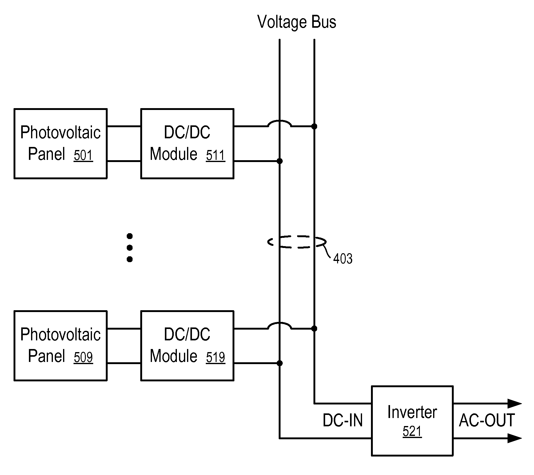
[0034]In one embodiment, a system is provided to combine an inverter or converter with high-efficiency DC-to-DC modules to deliver a stable voltage on a high voltage bus, thus a stable input voltage for the inverter, even through the energy and voltage supplied by the direct current energy sources, such as photovoltaic panels, may vary in a wide range. The stable voltage on the bus allows the system to run more efficiently and also to reduce the cost of the inverter.

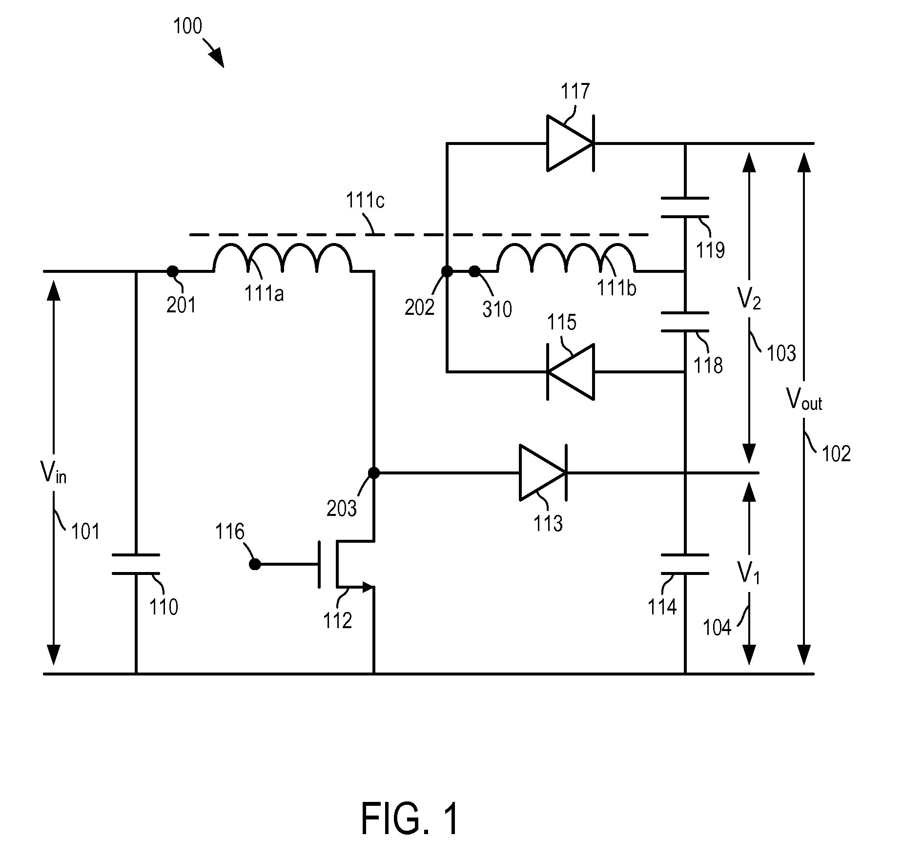
[0035]FIG. 1 shows a converter according to one embodiment. As...


PUM


Abstract

High voltage direct current systems to connect direct current energy sources to an alternating current system. In one aspect, a system includes a plurality of direct current modules having variable direct current inputs; an inverter; and a direct current bus to connect the direct current modules to the inverter, where the bus is configured to operate at a nominal voltage higher than 100 volts and to operate within 10 percent of the nominal operating voltage.

Description

RELATED APPLICATIONS[0001]The present application claims priority to provisional U.S. patent application Ser. No. 61 / 137,741, filed on Aug. 1, 2008 and entitled “Method and System of New Topology for Enhanced Ultra-Low-Cost, High-Efficiency, DC-to-DC Step-Up Converter,” the disclosure of which is hereby incorporated herein by reference.[0002]The present application is related to U.S. patent application Ser. No. 12 / 202,110, filed Aug. 29, 2008 and entitled “Step-Up Converter Systems and Methods,” and U.S. patent application Ser. No. 11 / 875,799, filed Oct. 19, 2007 and entitled “Method and System to Provide a Distributed Local Energy Production System with High-Voltage DC Bus.” The disclosures of these related patent applications are hereby incorporated herein by reference.FIELD OF THE TECHNOLOGY[0003]At least some embodiments disclosed herein relate to systems to connect direct current energy sources, such as solar panels, fuel cells, etc., to an alternating current system, such as a...

Claims


Application Information

Patent Timeline
IPC IPC(8): H02J1/10
CPCH02J1/102H02M3/157H02M3/33515H02M2001/0064H02M2001/007Y02E10/763H02J3/387H02J3/383H02J3/386Y02E10/563H02M2001/0077H02J2300/40H02J2300/30H02J2300/28H02J2300/24H02J3/381Y02E10/56Y02E10/76H02J3/46H02M1/0064H02M1/0077H02M1/007
Inventor AVRUTSKY, MORDECHAYHADAR, RONARDITI, SHMUEL
Owner NEWLIGHT CAPITAL LLC
Why Eureka
Try Eureka