Method and Device for Measuring an Angle at which a Magnetic Field is Aligned in a Plane Relative to a Reference Axis

a magnetic field and angle measurement technology, applied in the direction of magnetic field magnitude/direction, measurement device, instruments, etc., can solve the problems of high power consumption, disadvantages of relatively high-complex circuitry, and time-consuming scanning of many magnetic field sensors, so as to reduce the measurement-induced offset substantially, increase mixer bandwidth, and achieve the effect of reducing the measurement-induced offs

Active Publication Date: 2010-02-04
TDK MICRONAS GMBH
View PDF9 Cites 16 Cited by
  • Summary
  • Abstract
  • Description
  • Claims
  • Application Information

AI Technical Summary

Benefits of technology

[0015]It is advantageous if the pulse frequency of the switching clock signal of at least one magnetic field sensor is selected so that within a scanning cycle during which the measurement signal of this magnetic field sensor is coupled to the phase control loop, the orthogonal switching device assumes at least two and preferably four different switching statuses. By averaging the four possible polarities of the Hall sensors, it is possible to reduce a measurement-induced offset substantially. The mixer bandwidth increases due to the higher pulse frequency of the switching clock signal.
[0016]In another advantageous embodiment of the invention, the pulse frequency of the switching clock signal of at least one magnetic field sensor is selected so that the Hall sensor supply current of the magnetic field sensor changes its direction once after each rotation cycle of the rotation scanning signal. A spinning cycle is then completed after four rotation cycles of the rotation scanning signal. The spinning frequency fspin is then expressed as fspin=(frot / 4)=(fclk / 4N), wherein frot is the rotation frequency of the rotation scanning signal and fclk is the pulse frequency of a clock. The individual phase offsets of the magnetic field sensors are thus displaced from f=0 to fspin. A decimation filter can suppress these frequency components, thus enabling the averaging of the sensor offsets without additional expenditure.
[0017]Preference is given to the comparator having a clock signal input connected to a clock signal generator, wherein the clock signal generator is configured so that the pulse frequency of a comparator clock signal residing at the clock signal input is at least twice as large as the rotation frequency of the rotation scanning signal. The finding that the output signal of the frequency mixer oscillates with the frequency fmix=2 frot when the phase control loop is engaged is thus exploited. By the faster pulsing of the comparator, the angle of the magnetic field can be measured even more quickly.
[0018]In an advantageous embodiment of the invention, the follow-on oscillator has a number of oscillator outputs for digital oscillating signals phase-displaced relative to each other corresponding to the number of magnetic field sensors aligned with their measurement axes at right angles to each other, wherein a number of frequency mixers corresponding to the aforesaid number is arranged in the phase control loop, wherein each frequency mixer always has a first input connected to a measurement signal output of a magnetic field sensor allocated to the frequency mixer and a second input connected to one of the oscillator outputs, and wherein the mixer outputs of the frequency mixers are connected via an adding element, at least one low pass, and at least one synchronized comparator to the frequency control input of the follow-on oscillator. Preference is given to the scanning rate of the comparator having a frequency four times higher than the rotation cycle. The angle of the magnetic field can thus be measured even faster.
[0019]Mention should still be made that the measurement precision of the device can also be increased by always providing, for each measurement axis, several magnetic field sensors aligned parallel relative to each other, and by averaging the measurement signals of these magnetic field sensors.

Problems solved by technology

A disadvantage resides in the device in that the scanning of the many magnetic field sensors is time-consuming.
A further disadvantage resides in the fact that the non-degenerative, analog low pass must meet stringent requirements in terms of linearity and frequency response, which entails a considerable use of surface area on the chip and a high power consumption.
The relatively highly complex circuitry is also disadvantageous herein.
The calculation of the magnetic field angle results in a latency, which poses a disadvantageous when the device is used in a control circuit.

Method used


Image

  • Method and Device for Measuring an Angle at which a Magnetic Field is Aligned in a Plane Relative to a Reference Axis
  • Method and Device for Measuring an Angle at which a Magnetic Field is Aligned in a Plane Relative to a Reference Axis
  • Method and Device for Measuring an Angle at which a Magnetic Field is Aligned in a Plane Relative to a Reference Axis

Examples


Embodiment Construction

)

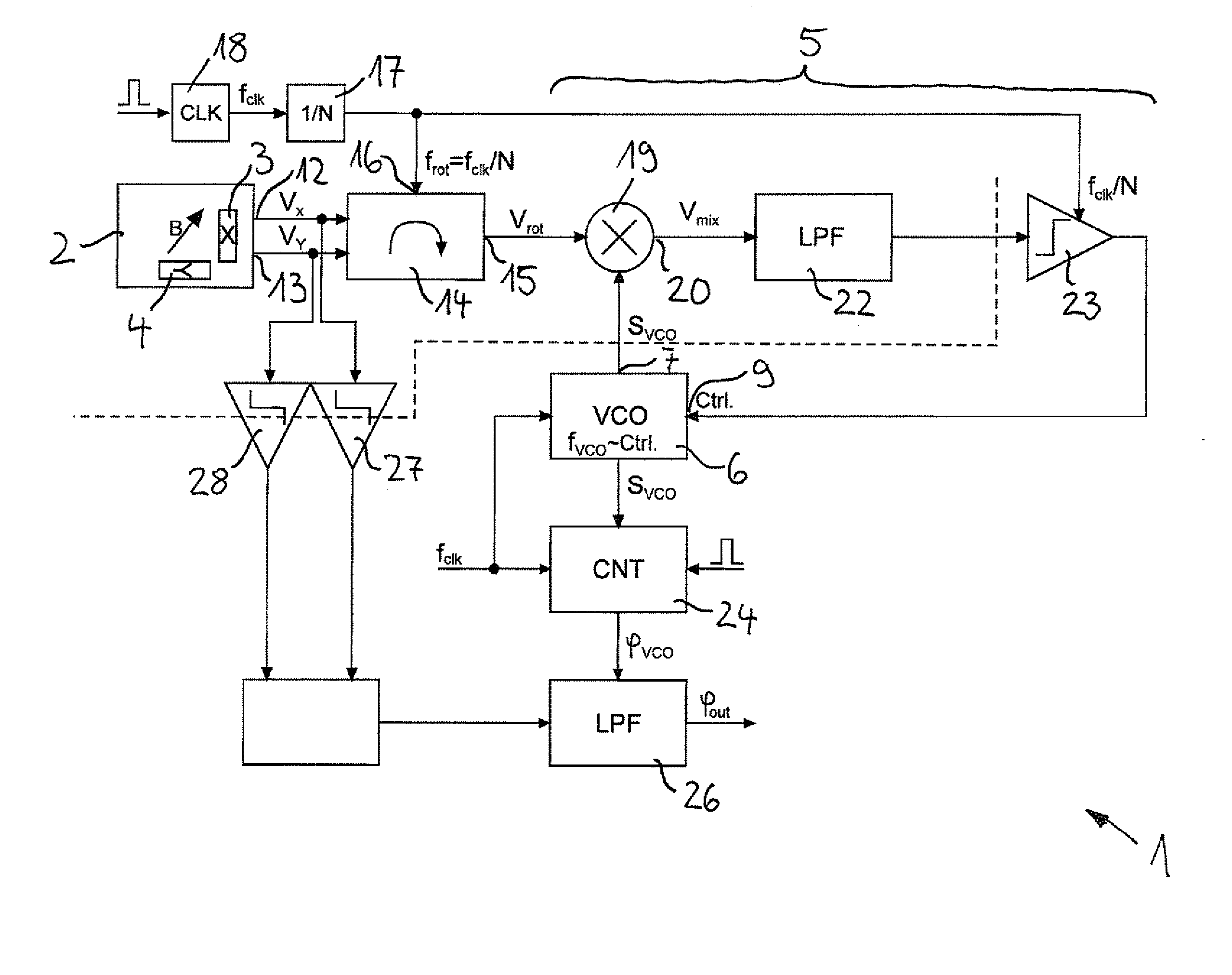
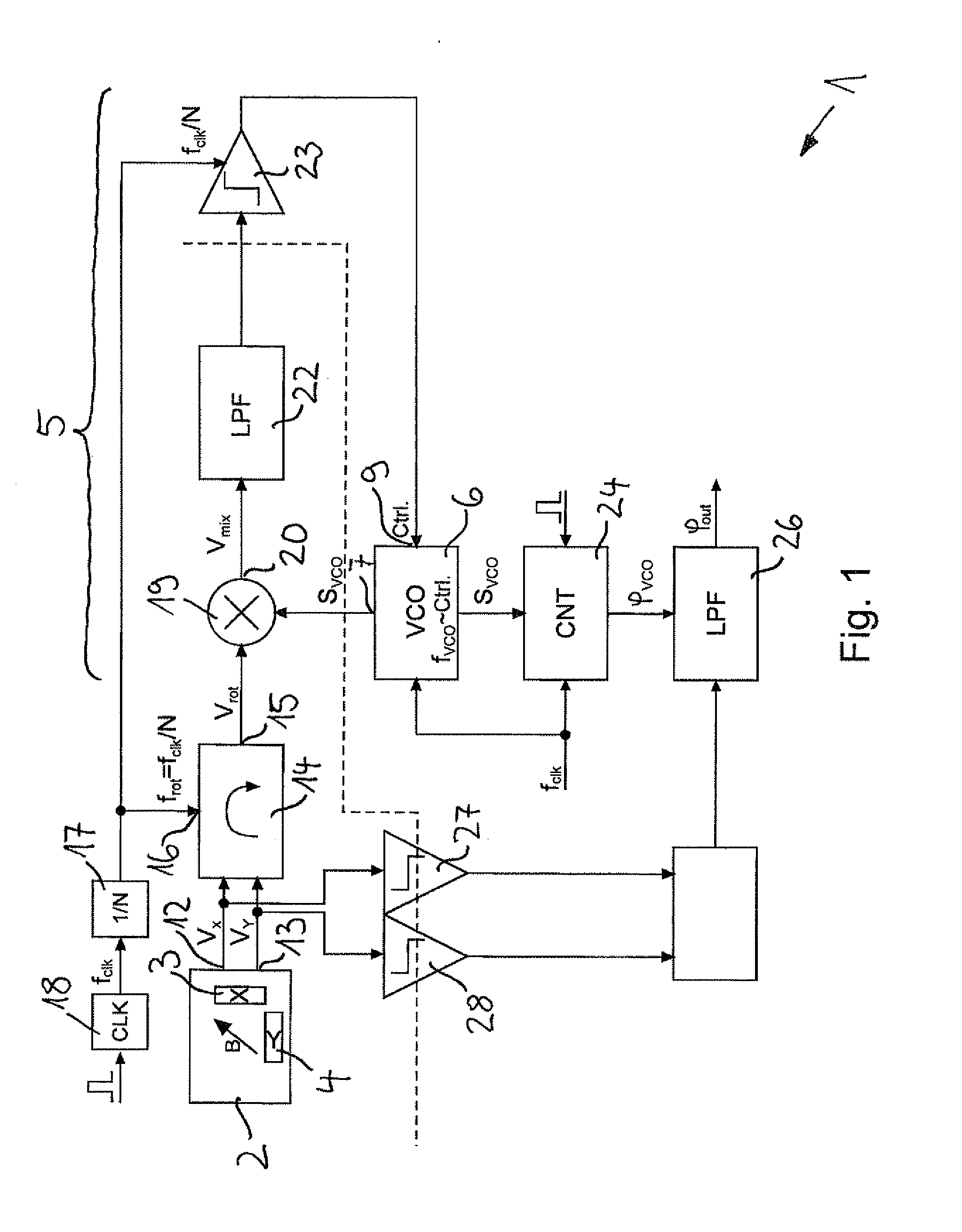
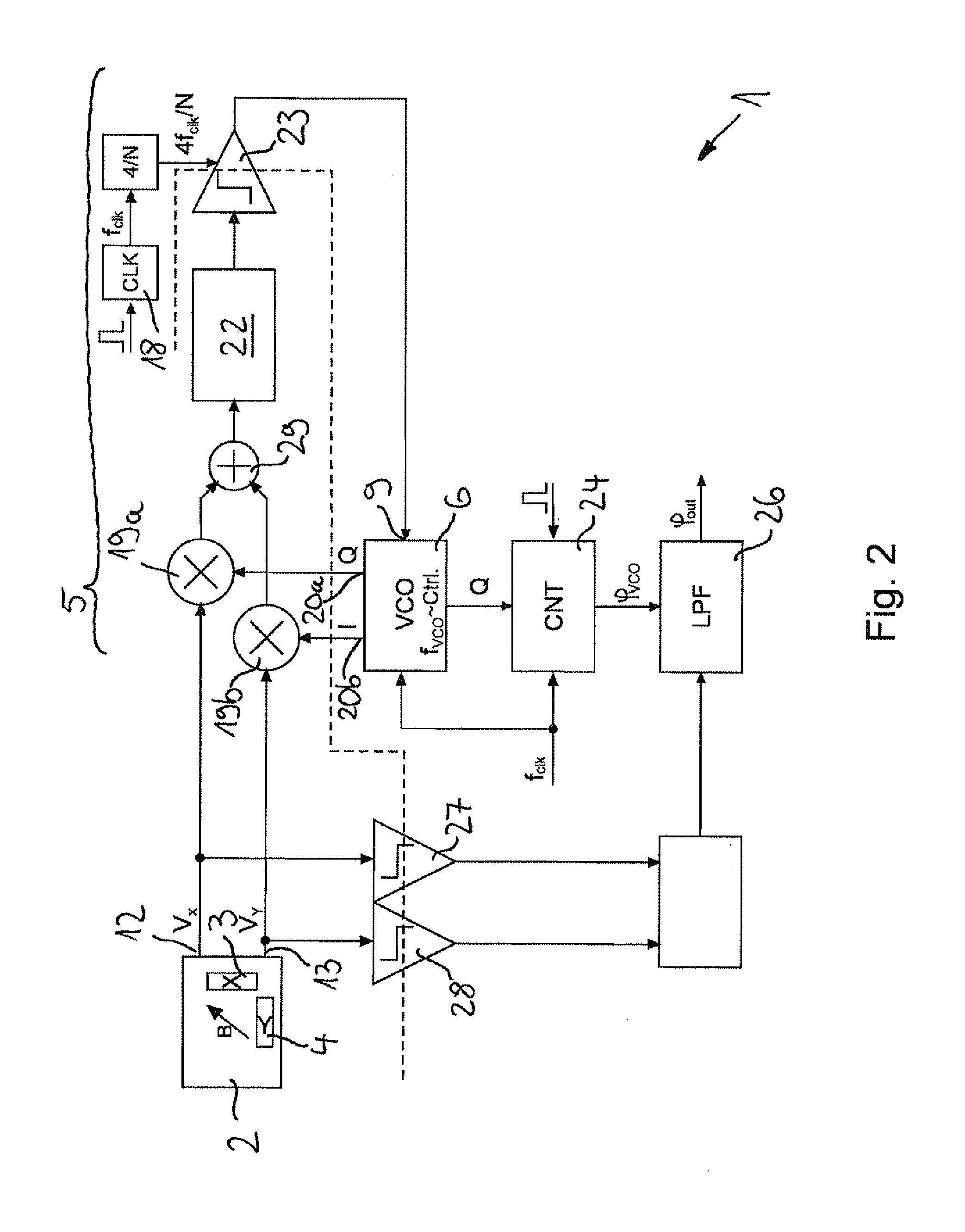
[0026]A device designated in its entirety by 1 for measuring an angle at which a magnetic field B is aligned in a plane 2 relative to a reference axis has two magnetic field sensors 3, 4 configured as Hall sensors, which are aligned with their measurement axes at right angles to each other. A first magnetic field sensor 3 is sensitive to an x-component of the magnetic field B and a second magnetic field sensor 4 is sensitive to a y-component of the magnetic field B.

[0027]The magnetic field sensors 3, 4 are integrated in a semiconductor chip, which is not shown in any greater detail in the drawing. They each have a Hall plate monolithically integrated in a semiconductor substrate, which is aligned with its extension plane perpendicular to the plane of the semiconductor chip.

[0028]In FIGS. 1 and 2 it can be discerned that the device 1 has a PLL phase control circuit 5 with a phase control loop, in which is integrated a follow-on oscillator 6. The follow-on oscillator 6 in the illustr...


PUM


Abstract

A device for measuring an angle at which a magnetic field is aligned in a plane relative to a reference axis has at least two magnetic field sensors, which are aligned with their measurement axes in and/or parallel to the plane and oriented at right angles to each other. The device has a PLL phase control circuit with a follow-on oscillator arranged in a phase control loop, which has at least one oscillator output for a digital oscillating signal The magnetic field sensors are coupled to the phase control loop in such a way that the digital oscillating signal is phase synchronous with a rotation scanning signal formed by rotary scanning of the measurement signals of the magnetic field sensors. The oscillator output is connected to a phasing detector for determining the phasing of the digital oscillating signal.

Description

BACKGROUND OF THE INVENTION[0001]1. Field of the Invention[0002]The invention relates to a device for measuring an angle at which a magnetic field is aligned in a plane relative to a reference axis, with at least two magnetic field sensors which are aligned with their measurement axes in and / or parallel to the plane and oriented perpendicular to each other. The invention further relates to a method for measuring an angle, at which a magnetic field is aligned in a plane relative to a reference axis, wherein a first magnetic field component and a second magnetic field component aligned perpendicular thereto are measured in and / or parallel to the plane.[0003]2. Description of Related Art[0004]A device of the aforesaid type is disclosed in Reymond, S. et al., “True 2D CMOS integrated Hall sensor”, IEEE SENSORS 2007 Conference, pp. 860-863, which has a semiconductor substrate in which are integrated so-called vertical Hall sensors as magnetic field sensors 64. The magnetic field sensors ...

Claims


Application Information

Patent Timeline
Patent Type & Authority Applications(United States)
IPC IPC(8): G01R33/02
CPCG01R33/0029G01R33/028G01R33/075G01R33/072G01R33/0283
Inventor MUTHERS, DAVID
Owner TDK MICRONAS GMBH
Why Eureka
Try Eureka